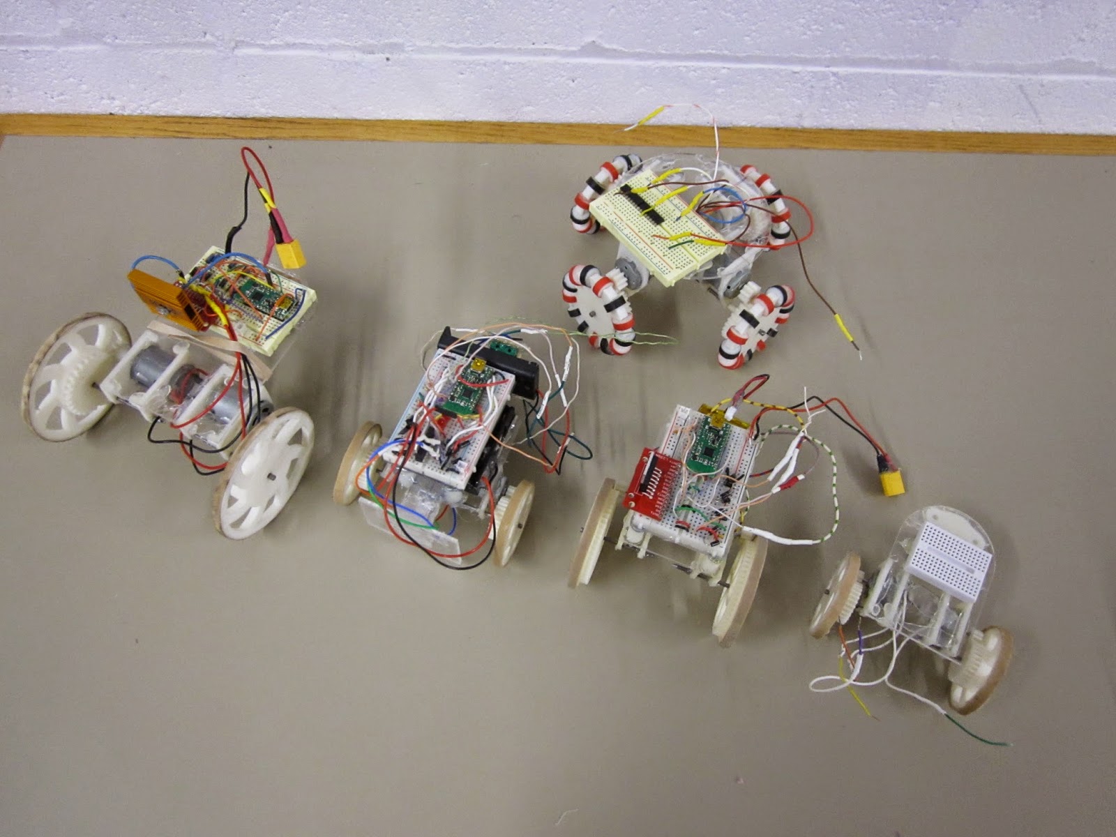
The 5 'models' of MOARbot that I've made so far. MOARbots doesn't really come in 'models' so I put that word in quotes. Overall the above robots represent my exploration of a bunch of different design elements. MOARbots as a project is just the framework/resources/suggestions one might need to pick and choose their own elements and make their own set.
When I have a need to create a set of robots though (for AI control, remote control games, whatever else), I do tend to want them to all be identical. So then I'll refine one design, and print out n many more. In that sense it has become convenient to refer to the designs as 'models.'
"Big Cart"
Above is the very first MOARbot. I sourced parts to make a full set of seven identical robots like this one. The motors are the very beefy RS-385SH by Mabuchi. These are geared with just a 3:1 ratio (I tried a 2:1 but with the battery weight, the thing stalled too easily). As a result it is very zippy. Notice the black marks on the rubber band tire--some Sector 67 members had fun driving this thing around quite a bit. Heat sink is definitely necessary. The stall current of each motor is 4 amps, which means that at full stall they will burn out the motor driver, which is spec'd at 4 amps total for both motor channels. The proper solution would be to use the current sensing pins to stop the motors when they draw too much current. The quick-fix solution I implemented at the time was to remind all the drivers that they should hit the brake key every time the robot ran into something.

"Omni Prototype 1"
This is the first omniwheel MOARbot prototype. It used 4 unknown motors pulled out of a bin. The omniwheel black and red 'beads' were spray coated with some products to make them more tacky, but that ultimately did not provide enough traction. A quick test showed moving a pair of motors took about 4 amps continuous current draw. The wheels slipped a lot on most surfaces as well. I came up with a much better design right after, but haven't yet finished work on that project (very very close though).

"Small Cart"
This is the smallest design so far. The motors were pulled from a bin, and only one worked. The robot was successfully able to drive in circles with 2 AA batteries (alkaline). This convinced me to try some smaller motors for similarly sized robots. If I were to go smaller than this, I'd switch away from 3D printed gears altogether and use rubber belts (like this robot that uses them with little CD drive motors). A robot like that could be built without any 3d printed parts, which would be appealing those who don't have access to 3d printing. A MOARbots project to source the parts for and build a set of those will happen most likely this year.

"Bumper Cart"
This is part of a set of 4 robots built around the FK-180SH. They are meant for playing remote controlled bumper cars, MarioKart style. The green pair of switches on the left are the target, and the acrylic panel on the left is the front of the robot. Robots race around the arena trying to hit the other robots' targets. After n hits to your target, your robot is out of the game (stops in its tracks) until the game is over and the players all agree to hit the reset button on their controllers. A pair of LEDs can be used to indicate robot 'health.' Why only 2? There are only 2 'high current' (20mA) output pins on the Wixel, and that breadboard was getting too crowded for me to start adding in some transistors.
Unfortunately the bumper carts did have one minor issue--for reasons not yet determined, the cart couldn't actually move under its own weight with the full circuit hooked up, but could move when the batteries were connected directly to the motor terminals instead. I will have to do some science to it, but I bet putting a nicer battery (2 or 3 cell lithium polymers) will fix the problem.
One cool but not completely necessary feature of the bot above and the bot below is a disconnect-able breadboard. The breadboard sits on top of three standoffs, and is held in place by magnets. The motor and battery leads are long enough to allow the breadboard to be moved around. I like this system because it means I can work on the circuit without risking pushing down too hard on the robot frame (this is mostly a fear because the diodes I bought have very thick leads and the required force to insert them into the breadboard is high).

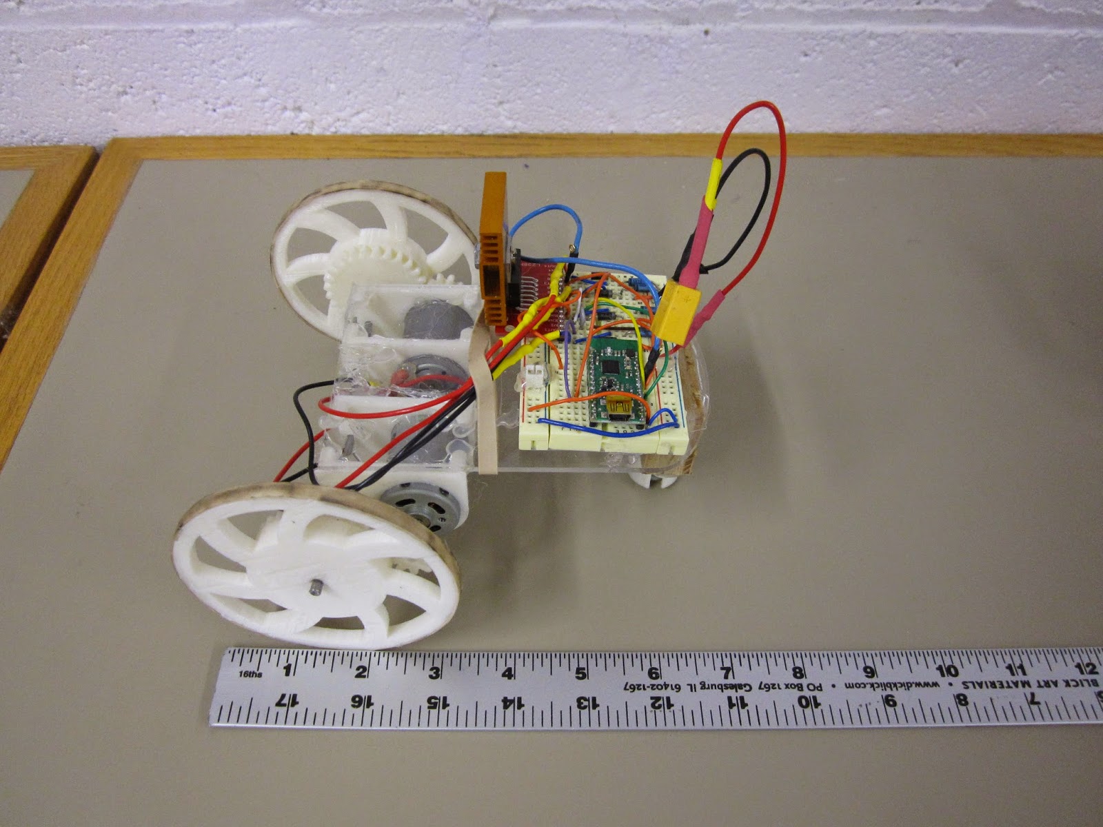
"Independent Study Cart"
This is the cart I just finished for an independent study I'm leading at the university. The key point of this design is to use the small, cheap, and ubiquitous "130" sized motors, like this one, though you can get them cheaper on eBay if you buy in bulk from China. Knowing that these motors would be a lot less powerful than the previous ones I had used, I needed to stick as many teeth as possible on the wheel. To do that without pushing my luck on 3D printer resolution and gear alignment issues, I made the gear ring as large as possible, so now the spokes are actually on the inside of the gear. The results are good, in terms of having big safety margins on gear alignment and robot pushing force. I put a very heavy 2,200 mAh battery pack on it and it moved quite well. I will probably source significantly lighter batteries for next week's order of remaining parts.
Now I just have to source the parts for 9 more, and work out nicer battery compartments, wiring harnesses, and ID tag standoffs for this bot. Then there is also some code I need to clean up and finish up. I'm pretty excited to see this project move to the next step finally! Though I will be playing around with new omniwheel and belt-driven robots eventually, for the next window of time my focus will be entirely on the robot brains (code and algorithms) side of things.