Sunday, December 15, 2019

Endless time sink projects!

It has been a difficult but exhilarating semester.

We made a makerspace! Here it is all packed up because we needed to move it to another location last week.


Thinking about the makerspace ate up all my waking hours since it opened. After a few months I started to feel unsettled by how little other identity I had left. Makerspace director is an all-encompassing role in two senses--having to do nearly everything related to it, having everything you do be related to it. You only ever get to make one thing, the makerspace.

But at the end of the semester I have found a little time to think and regroup. I need to make things in addition to making the makerspace. I'm not one to do anything casually enough to call it a hobby. So... I've started up the Blender Graphic Novel project again.

Because it seemed like complete and utter folly to reopen that project (another infinite time sink), first I tried lots of things, like watching movies and going out to eat with friends. But nothing else seemed to plug the hole.

Comic from Dresden Codak

So, just like with the makerspace project, I try the impossible thing anyway, then it doesn't always go well, then in private I cry and get angry, and then I use that anger to rhetorically dare myself to give up, which I will never do, so I swear stubbornly to try again, and the cycle repeats. And sometimes on a night like tonight I even make some promising incremental progress.

Incremental progress. Just testing out a few concepts

What I've learned in re-opening the project for the first time since 2016:

I'm still relying heavily on Blendswap for assets, but it feels like that website/community has lost some momentum. The environment above is from https://www.blendswap.com/blend/10299
Most of the assets I had found in the past still seem to be there so that's good, but the search function is pretty bad and all my Likes/Collections from before are now all empty.

In 2018 Manuel Bastioni decided to try raising funds for the MBLab project, but after about three days he gave up and shut the whole project down. It seems he expected a large audience to materialize (with not much thought given to advertising) and that most of them would immediately donate. The project is now on Github https://github.com/animate1978/MB-Lab

Marvelous Designer is up to version 9 from version 6, and it seems the same. I'm a little frustrated with it but at the same time it is the only tool that does what I need, and it gets good results (but slowly due to clunky workflow).

The sewing pattern community is still disappointing. Everybody seems only interested in making a few bucks here and there for the patterns in their collection. Very few community seems really attuned to concepts like public domain, digitally archiving historical patterns, getting into the nitty gritty of patent, trademark, copyright law, first sale doctrine, and understanding how it does and doesn't potentially affect sewing patterns and fashion. I wanted to try paying for ready-made Marvelous Designer garment assets but found very few for sale.

Blender Internal is gone in Blender 2.8 and I'm using Eevee instead. Freestyle still works, and is still pretty slow. Eevee is much faster than Cycles and I really don't need raytracing for the style I'm going for. I can use viewport rendering which helps workflow, so long as I keep the number of vertices sane.

Big directions to explore next:
- Hair...still difficult. Need to practice a bit.
- How to effectively storyboard so I don't waste time on scenes and assets I don't need, and so that the pages and chapters are cohesive (visually, and from a storytelling perspective)

https://www.reddit.com/r/funny/comments/eccj2/how_to_draw_an_owl/

Saturday, June 22, 2019

Balloon Battle

I wanted to run a team-building activity this summer in the makerspace, and settled on the format of a robot Balloon Battle.

After the activity I spent an evening learning Adobe Premiere and putting together a video. So this was a mix of a workshop and a video editing project.

Shout-out to M5 staff and volunteers for helping with and participating in this event.

Here's the video!


Saturday, June 8, 2019

Nonholonomic Driving Robots Revisited: RRTs

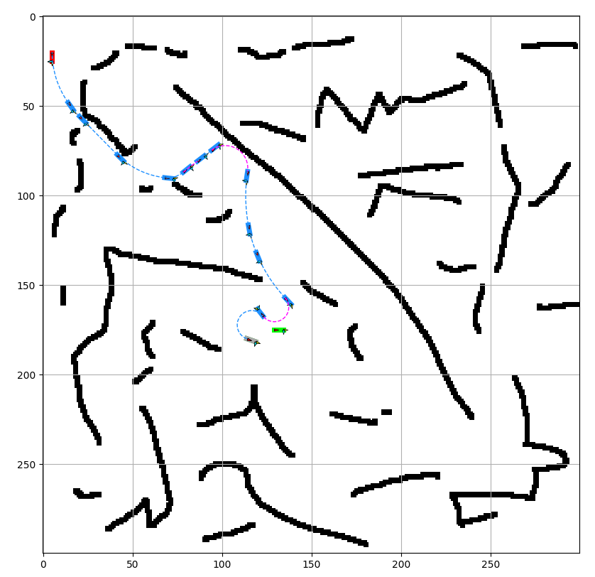
"Screenshot of RRT"

Back in 2017, before a major geographical move and career change, I was working on a project where I built and wrote an A* based path planning algorithm for a nonholonomic robot:
http://buildingfriends.blogspot.com/2017/06/indoors-navigation-robot-driving.html

In the process of doing research for that project, I had come across the concept of Rapidly Exploring Random Trees:
https://en.wikipedia.org/wiki/Rapidly-exploring_random_tree

I tested one simple implementation on GitHub (I can't remember which) and thought about what would be involved for using it for my path planning approach. I decided I would need to consider an extension and probably would not be successful with a basic RRT alone. I identified Theta* RRT as a promising technique for solving my particular path planning problem.
http://idm-lab.org/bib/abstracts/papers/icra16.pdf

But I ran out of time and confidence in my ability and went with the what I already understood fairly well, which was A*, and wrote about it in this blog (but never got around to publishing it on GitHub).

Since I moved in 2017, nearly all my projects involve making makerspaces. Instead of making projects, I help other people create projects. And recently, rather than helping other people create projects, I create systems to help people help other people to create projects. A big theme in my life is institutional sustainability/long term institutional survival/development of infrastructure that is not highly dependent on a single individual's expertise, presence, and commitment. I am trying to automate my job (not that I don't enjoy doing it, but it feels like the responsible thing to do; too many makerspaces and other institutions have serious existential risk posed to them by there being one leader upon whose shoulders everything rests).

 I haven't had too much time to collect my thoughts into a post, though I will keep trying in the future.

I revisited Theta* RRT nearly two years later in the context of a graduate level robotics class I signed up for, perhaps foolishly.

The robotics class was excellent, but a huge time sink. For the first time in two years I wasn't teaching a three hour lab based class once a week, so I figured that freed up about 10 hours a week to spend on this. The professor for this class said to expect to spend 5 hours a week on average on the class, so I figured I was good...

There were 5 assignments due over the 13 week semester. I spent only 15 hours from start to finish on at least two of them (but those were the easiest ones). If they had all each taken 15 hours, 15 hours * 5 assignments / 13 weeks is about 5.8 hours a week. But many of them took me much, much longer than 15 hours. I probably spent 50-60 hours on the Theta* RRT project. On top of that were required and optional readings. These weren't really enforced. I hate to admit I did nearly none of those readings. I was really struggling to balance my job and my desire to perform really really well in this class, and so I tried to limit my time expenditure to only those things that directly would affect my grade in this class. I guess when I was a kid I had to make compromises like 'do well in school' vs. 'socialize and have fun.' But now I make mostly compromises like 'do well in school' vs. 'spend more time on work' and I'm starting to really feel like an adult...

Fast forward to the end of the Spring 2019 semester. I'm trying to finish my final project, for which I've chosen to implement Theta* RRT in Python, and also my final other assignment, which is an implementation of RRTs in C++. I pushed all my other commitments forward and sat at my dining room table working for 15 hours straight on the last day, accidentally causing what might be permanent nerve damage to one of my legs (it has been a month and still I have a large area without much skin level sensation on my shin). I do feel that it was worth it, though if I had known I would have gotten a more comfortable chair which would have prevented that from happening. I would have also found a way to make more time for this project in the weeks prior.

User-uploaded image: Screenshot+from+2019-05-07+19-56-40.png

The rapidly exploring random tree works like this (glossing over details):

There is a starting position and orientation for the car (red, above) and we want it to reach the goal position and orientation (green, above). The car can't steer very sharply; it has a limited turn radius. There are many ways it could reach the goal, but it is impossible to search them all, because the x and y position, as well as the angle of the car, are all continuous real variables, so infinite and uncountable.

So at every step of this algorithm, which we will repeat until we find some path that drives us to the goal within a tolerance, we will randomly choose some x,y position and car angle.

We're going to keep track of paths in this process in the form of a tree, branching from the red car (starting node). We'll identify the configuration in the tree nearest to the new random configuration (note that in the beginning, the only thing in the tree is the starting node).

Then we will try to drive to the new random configuration. We probably can't find a way to drive to the new configuration exactly, but we'll drive towards it and wherever we land, we'll add that to the tree, keeping track of that steering path we used to get there. We'll always check to see if we made it close enough to the goal, and if we did, we'll extract the path from the tree that got us there.

The entire tree is shown in black, and the extracted solution path in blue.

User-uploaded image: Screenshot+from+2019-05-07+19-58-08.png
One of the very lucky trials for the plain RRT. Note how it considered backing up in one iteration, but otherwise explored directly to the goal.

Parallel parking:
User-uploaded image: Screenshot+from+2019-05-07+20-23-10.png

User-uploaded image: Screenshot+from+2019-05-07+20-18-34.png


The Theta* RRT project took longer than expected and I didn't complete everything I wanted to put into it. So I'll leave a more in depth post about it for after I get around to revisiting it and completing all the parts I wanted to complete. You can follow along on GitHub:
https://github.com/eshira/theta-rrt

Tuesday, January 22, 2019

Rhombic Enneacontahedron Post #2

Alright, here's the code. It is a total mess, but I knew I just wasn't going to get around to even starting to clean it up, so I just committed it before I forget about it (and likely struggle to locate it in the future).

https://github.com/eshira/polyhedra/tree/master/Rhombic-Enneacontahedron

I figured out the degree of freedom I forgot about. When you truncate, you can move new vertices in along old edges some amount, which you can choose. I split edges in three, moving each new vertex in by a third (see the diagram from wikipedia that I included in the previous post). Splitting in three makes sure you create regular hexagons for the soccer ball step (the truncated icosahedron). You don't have to create regular hexagons, and by modifying this you can make slim and broad rhombi, as shown in the images below.

This explains why I didn't match the values for the angles that I found on Wikipedia for the rhombic enneacontahedron. I suspect that most of these rhombic enneacontahedrons people make come from just a few instructional guides or paper folding guides online, which often refer to slim and broad rhombi, so probably they aren't making regular hexagons in the truncation step, which seems to yield very similar rhombi so that you can't easily call them broad or slim.

Extreme cases caused by changing parameter of truncation step seem to be less 'round'


Here's the final 3D printed assembly, after gluing in the magnets. The edge length on the edges the white and red tiles share are 2cm long, for reference


It would be fun to print the exaggerated versions with very broad and very slim rhombi at some point in the future.

Want to make your own? The code isn't super clean, so the steps at a high level:

  • If you want to modify the truncation, you'll need to locate that section of the code, modify the appropriate line, and then get the code to spit out all the info you need on the angles and side lengths that are needed by the OpenSCAD script. There are a bunch of poorly commented areas where you can follow my pattern--I was working quickly and I just didn't make it easy to use yet. Sorry!
  • If you keep the angles as in the OpenSCAD script, you'll make a shape like the one I made. You need to make sure the user controlled side length is the same for the tiles of type A and B. You also need to make sure you match the magnet info between those two types of tile.
  • You can do this with just one magnet per edge if you want to save on magnets, though it won't be as strong and the tiles can pivot until locked into place by neighbors. You will need to go through my code because I didn't make it parametric either
Easiest way to do it? Keep everything exactly the same as my OpenSCAD code, render the STL and slice it for your 3D printer. Get at least 90*4 magnets, 3mm diameter by 2mm height, axially aligned. The magnet diameter and depth values in the script might still need to be adjusted to get a nice fit, depending on your 3D printer.

Wednesday, January 9, 2019

Rhombic Enneacontahedron

Over a year ago I decided the next 3d printed magnetic tile based polyhedron I would create would be the rhombic enneacontahedron.

In the past I created shapes mostly by looking up the dihedral and face vertex angles from the internet. Only for the most recent one, the parametric pyritohedra/dodecahedron script, I generated the points of the whole polyhedron and manipulated them, before creating the individual faces as tiles. For the trapezohedra, some of the ones I attempted to create had the wrong angles, and it wasn't clear to me if the issue was in the angles I had gotten from the internet or if my OpenSCAD script contained some errors. I decided though that the right way forward would be to build the tiles as I did in the pyritohedra script, by creating the full polyhedron and then computing the angles for the tiles myself.

I had just learned about Conway polyhedron notation and considered that the right way to build this would be to use that concept. But I didn't end up getting a library for Conway polyhedron notation, or creating a library for these operators. Instead I did everything a bit less abstractly and elegantly than I'd have liked, but I think that's normal to expect for a first draft.

I switched from OpenSCAD to python at this point, because I find it impossible to do anything with for loops in OpenSCAD (highly inefficient and slow). For creating polygons in 3D space I used pyny3d, which is already integrated with matplotlib for drawing. And I use numpy for math stuff. I finally switched to python 3 for this and wrote every print statement incorrectly the first time...

We begin with the icosahedron:


For the icosahedron I started with a list of 12 vertices as listed on various places online.
Each of the below descriptions of vertices in format (x, y, z) expands into four vertices given there are ± options in two of the dimensions for each one.
(0, ±1, ± φ)
(±1, ± φ, 0) 
(± φ, 0, ±1)
Where φ (phi) is the golden ratio, 0.5*(1+sqrt(5))


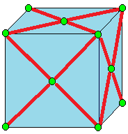
The first goal is to truncate the icosahedron. I came up with my implementation of truncation by interpreting the picture and one line description from Wikipedia, which I'll include below, and is drawn on an example cube:


Truncate cuts off the polyhedron at its vertices but leaves a portion of the original edges.[10]

I describe truncation like this:
For each vertex, find every edge is is a part of, and create a vertex one-third of the way inward on that edge. The new shape's vertices are the newly created vertices.
The new shapes faces I separate into two categories.
The first category are created by drawing edges between all the new vertices spawned off a single old vertex. In our case, the icosahedron has vertices at 5-edge intersections, so these are five sided shapes (pentagons).
The second category are the truncated versions of the original faces. For each original face, consider each original vertex. That original vertex spawned some new vertices, but only two lie on this original face that we are currently evaluating. The new face that will replace the old face is defined by all of these new vertices corresponding with the old face, that still lie on this face.
We had triangular faces with the icosahedron, so with two vertices per original vertex multiplied by three original vertices, we have created six vertex faces (hexagons).


The truncated icosahedron is a soccer ball, shown above in red pentagons and blue hexagons.

Now we must run a join operation on the truncated icosahedron. Again, expanding from only the short wikipedia entry:

Join creates quadrilateral faces. 

That's not a lot to go on... To better understand it I considered a similar operation, kis:


Kis raises a pyramid on each face

Okay, so join is like kis without the original edges. The old vertices can stay put, but the new vertices, created in the middle of each face, need to be lifted. But by how much to lift them? And where to put them to center them on the face?

I had gone over the math for finding the vertex on the face, when I went over the math to define the dual operator. Luckily for me the pentagons and hexagons are regular, so I could just take the mean of the points in this case.

The insight for how to lift the vertices came from the symmetry. Some of the newly created quadrilaterals will go from one hexagon center point to another hexagon center point. To preserve symmetries, I assumed that all hexagon center points will be lifted the same amount. I drew a quick diagram to figure out the computation for how far to raise them in order to make all four points coplanar (otherwise, we don't have a valid face. At time of writing, this site which I enjoyed using in the process of learning about Conway operators, seems to have some nonplanar 'faces', so it looks very strange).

New quadrilaterals connecting old hexagon centers to old pentagon centers must also be created, utilizing two old vertices that come from the edge shared between the adjacent hexagon and pentagon. Since we finalized the height of the point raised off the hexagon center, and we know the two points from the shared edge are the same as they were before, the only thing to do is compute how far to raise the pentagon center along the norm of the pentagon face until it lies on the plane defined by these other three points.

To draw the faces I needed to keep track of which faces were adjacent to which other faces, so I created some dictionaries and populated them with simple for loops because I'm not concerned about optimizing my code at all given what I'm using it for.


The next step was to compute and print out the angles I needed to create a tile. This was just a question of identifying the right vertices, edges, and vectors and computing various norms and cross products.

For the tiles I moved back to OpenSCAD. I reused my rhombic triacontahedron tile code for the parallelogram faces (red). For the kite faces (blue) I created some new, but very similar code.

Here's the info printed out, there's definitely going to be some rounding error but not significant to my purposes.

There are two dihedral angles:
Red to blue faces: 159.4455573432933 degrees
Blue to blue faces: 160.81186354627906 degrees

The red parallelogram faces have an acute interior angle: 56.67993474152847 degrees
And the complement (computed just to check if correct, but not needed as additional info): 123.32006525847153 degrees

The blue kites are more interesting. The skinniest angles are the tips of the five pointed stars they create.
56.67993474152846 degrees

The opposite angle, which lies in the middle of those stars where they meet in groups of five, is close but certainly not the same angle:
69.7316519531762 degrees

It is a kite, so symmetric in this remaining dimension, and both of these larger angles are the same:
116.7942066526476

This didn't seem to match the info on Wikipedia and I'm also not seeing such a clear distinction between 'slim' and 'broad' rhombi. I wonder if I did something wrong, though so far everything is internally consistent for my construction. I wonder if there's an assumption I made that got rid of one degree of freedom....

Finally I needed some info about the edges. The red edges are all the same length. And, they match the length of the slightly longer of the edges of the blue tiles. The other type of edge is the ones that the blue tiles share with each other. I call this a 'short edge.' 

I computed a long side: 0.4339800705873414
And a short side: 0.36037602329028573

And the ratio of short to long as their ratio:
0.36037602329028573/0.4339800705873414

I ordered a few kinds of magnets in sufficient quantity (I need 90 faces * 4 magnets a face, but I might also double up and do 2 magnets an edge or 8 magnets a face). While I wait, I am 3D printing some tiles just to tape together and see if the angles work. So far it is looking promising.

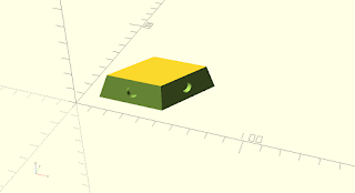
parallelogram faces model, shown with magnet holes


 kite faces model, shown without magnet holes


They look fairly similar to the untrained eye...

Taped together with masking tape as a test....red parallelograms and white kites. They were all printed in white, and then I used a sharpie to color the parallelograms in red.


A five pointed star of kites.


Since these come together nicely, I think I have all the vertex angles and the dihedral angles correct.

I've always used either masking tape (testing) and magnets (super-glued into the slots) to construct these, but somebody who printed one of my designs and tried gluing them together noticed that there appeared to be an accumulating offset problem that grew as the shape was constructed and made it so it wouldn't close. It seems that you need to leave some flexibility in order to distribute errors (that come from the manufacturing process or mis-alignment during assembly). Some ideas I haven't tried include: putty, velcro.

Once I've had a chance to build the whole thing, I'll follow up with another post, and clean up the code and commit it to GitHub as well.