Over a year ago I decided the next 3d printed magnetic tile based polyhedron I would create would be the
rhombic enneacontahedron.
In the past I created shapes mostly by looking up the dihedral and face vertex angles from the internet. Only for the most recent one, the parametric pyritohedra/dodecahedron script, I generated the points of the whole polyhedron and manipulated them, before creating the individual faces as tiles. For the trapezohedra, some of the ones I attempted to create had the wrong angles, and it wasn't clear to me if the issue was in the angles I had gotten from the internet or if my OpenSCAD script contained some errors. I decided though that the right way forward would be to build the tiles as I did in the pyritohedra script, by creating the full polyhedron and then computing the angles for the tiles myself.
I had just learned about
Conway polyhedron notation and considered that the right way to build this would be to use that concept. But I didn't end up getting a library for Conway polyhedron notation, or creating a library for these operators. Instead I did everything a bit less abstractly and elegantly than I'd have liked, but I think that's normal to expect for a first draft.
I switched from OpenSCAD to python at this point, because I find it impossible to do anything with for loops in OpenSCAD (highly inefficient and slow). For creating polygons in 3D space I used
pyny3d, which is already integrated with
matplotlib for drawing. And I use
numpy for math stuff. I finally switched to python 3 for this and wrote every print statement incorrectly the first time...
We begin with the icosahedron:
For the icosahedron I started with a list of 12 vertices as listed on various places online.
Each of the below descriptions of vertices in format (x, y, z) expands into four vertices given there are ± options in two of the dimensions for each one.
(0, ±1, ± φ)
(±1, ± φ, 0)
(± φ, 0, ±1)
Where φ (phi) is the golden ratio, 0.5*(1+sqrt(5))
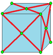
The first goal is to truncate the icosahedron. I came up with my implementation of truncation by interpreting the picture and one line description from Wikipedia, which I'll include below, and is drawn on an example cube:
Truncate cuts off the polyhedron at its vertices but leaves a portion of the original edges.[10]
I describe truncation like this:
For each vertex, find every edge is is a part of, and create a vertex one-third of the way inward on that edge. The new shape's vertices are the newly created vertices.
The new shapes faces I separate into two categories.
The first category are created by drawing edges between all the new vertices spawned off a single old vertex. In our case, the icosahedron has vertices at 5-edge intersections, so these are five sided shapes (pentagons).
The second category are the truncated versions of the original faces. For each original face, consider each original vertex. That original vertex spawned some new vertices, but only two lie on this original face that we are currently evaluating. The new face that will replace the old face is defined by all of these new vertices corresponding with the old face, that still lie on this face.
We had triangular faces with the icosahedron, so with two vertices per original vertex multiplied by three original vertices, we have created six vertex faces (hexagons).
The truncated icosahedron is a soccer ball, shown above in red pentagons and blue hexagons.
Now we must run a join operation on the truncated icosahedron. Again, expanding from only the short wikipedia entry:
Join creates quadrilateral faces.
That's not a lot to go on... To better understand it I considered a similar operation, kis:
Kis raises a pyramid on each face
Okay, so join is like kis without the original edges. The old vertices can stay put, but the new vertices, created in the middle of each face, need to be lifted. But by how much to lift them? And where to put them to center them on the face?
I had gone over the math for finding the vertex on the face, when I went over the math to define the dual operator. Luckily for me the pentagons and hexagons are regular, so I could just take the mean of the points in this case.
The insight for how to lift the vertices came from the symmetry. Some of the newly created quadrilaterals will go from one hexagon center point to another hexagon center point. To preserve symmetries, I assumed that all hexagon center points will be lifted the same amount. I drew a quick diagram to figure out the computation for how far to raise them in order to make all four points coplanar (otherwise, we don't have a valid face. At time of writing,
this site which I enjoyed using in the process of learning about Conway operators, seems to have some nonplanar 'faces', so it looks very strange).
New quadrilaterals connecting old hexagon centers to old pentagon centers must also be created, utilizing two old vertices that come from the edge shared between the adjacent hexagon and pentagon. Since we finalized the height of the point raised off the hexagon center, and we know the two points from the shared edge are the same as they were before, the only thing to do is compute how far to raise the pentagon center along the norm of the pentagon face until it lies on the plane defined by these other three points.
To draw the faces I needed to keep track of which faces were adjacent to which other faces, so I created some
dictionaries and populated them with simple for loops because I'm not concerned about optimizing my code at all given what I'm using it for.
The next step was to compute and print out the angles I needed to create a tile. This was just a question of identifying the right vertices, edges, and vectors and computing various norms and cross products.
For the tiles I moved back to OpenSCAD. I reused my rhombic triacontahedron tile code for the parallelogram faces (red). For the kite faces (blue) I created some new, but very similar code.
Here's the info printed out, there's definitely going to be some rounding error but not significant to my purposes.
There are two dihedral angles:
Red to blue faces: 159.4455573432933 degrees
Blue to blue faces: 160.81186354627906 degrees
The red parallelogram faces have an acute interior angle: 56.67993474152847 degrees
And the complement (computed just to check if correct, but not needed as additional info): 123.32006525847153 degrees
The blue kites are more interesting. The skinniest angles are the tips of the five pointed stars they create.
56.67993474152846 degrees
The opposite angle, which lies in the middle of those stars where they meet in groups of five, is close but certainly not the same angle:
It is a kite, so symmetric in this remaining dimension, and both of these larger angles are the same:
116.7942066526476
This didn't seem to match the info
on Wikipedia and I'm also not seeing such a clear distinction between 'slim' and 'broad' rhombi. I wonder if I did something wrong, though so far everything is internally consistent for my construction. I wonder if there's an assumption I made that got rid of one degree of freedom....
Finally I needed some info about the edges. The red edges are all the same length. And, they match the length of the slightly longer of the edges of the blue tiles. The other type of edge is the ones that the blue tiles share with each other. I call this a 'short edge.'
I computed a long side: 0.4339800705873414
And a short side: 0.36037602329028573
And the ratio of short to long as their ratio:
0.36037602329028573/0.4339800705873414
I ordered a few kinds of magnets in sufficient quantity (I need 90 faces * 4 magnets a face, but I might also double up and do 2 magnets an edge or 8 magnets a face). While I wait, I am 3D printing some tiles just to tape together and see if the angles work. So far it is looking promising.
parallelogram faces model, shown with magnet holes
kite faces model, shown without magnet holes
They look fairly similar to the untrained eye...
Taped together with masking tape as a test....red parallelograms and white kites. They were all printed in white, and then I used a sharpie to color the parallelograms in red.
A five pointed star of kites.
Since these come together nicely, I think I have all the vertex angles and the dihedral angles correct.
I've always used either masking tape (testing) and magnets (super-glued into the slots) to construct these, but somebody who printed one of my designs and tried gluing them together noticed that there appeared to be an accumulating offset problem that grew as the shape was constructed and made it so it wouldn't close. It seems that you need to leave some flexibility in order to distribute errors (that come from the manufacturing process or mis-alignment during assembly). Some ideas I haven't tried include: putty, velcro.
Once I've had a chance to build the whole thing, I'll follow up with another post, and clean up the code and commit it to GitHub as well.