Showing posts with label robots. Show all posts
Showing posts with label robots. Show all posts
Friday, March 17, 2017
Painting Robot Compilation
A while back somebody donated an old robot arm kit to Sector67. I built a small model of it with glue, tape, foamboard, and potentiometers, and hooked it up to an Arduino. The project is very simple, but it has been very popular at science fairs (and has survived many hours of use requiring minimal fixes only). Here's a compilation video.

Wednesday, February 15, 2017
Simple Educational Robot Arm with Inverse Kinematics
The point of this project is to test a lesson that covers the theory and construction of a simple, two degree of freedom robot arm that moves in a plane and is controlled by specifying the X and Y position of the end of the arm (the 'hand'), rather than by specifying the angles of the two servos directly.

I ran most of this lesson last year at a summer camp, but due to limited time/high variance in math background of the students, we weren't able to reach the point I wanted to reach. (Really what happened is that I volunteered to have another class join my class for three hours for an activity, which meant a lot of my prep time ended up being soldering leads on more potentiometers...)
This activity seemed promising so I went through it again, at a less hectic pace this time, to try and make a list of the tricky 'gotchas' that would be useful to provide as hints if the goal was to have most of the students complete the project in the class time allotted.
Students who have completed a class covering trigonometry should have sufficient mathematical background to cover the math, which is described nicely on this page: http://www.learnaboutrobots.com/inverseKinematics.htm
A partial list of the tricky parts students may get stuck on (beginners tend to try to build the whole thing at once; a few compound problems can make it very difficult to debug):

I did mount the second servo flipped downwards, to reduce overall height of the assembly. That was a mistake in hindsight, because it means the arm can collide with itself.
Here's a video of the test arm I built, demonstrating that it more or less works correctly.
Finally here's the sketch. It isn't clean or commented...but I've decided it is better to share these things than to never get around to it at all.
Arduino Sketch for this project

I ran most of this lesson last year at a summer camp, but due to limited time/high variance in math background of the students, we weren't able to reach the point I wanted to reach. (Really what happened is that I volunteered to have another class join my class for three hours for an activity, which meant a lot of my prep time ended up being soldering leads on more potentiometers...)
This activity seemed promising so I went through it again, at a less hectic pace this time, to try and make a list of the tricky 'gotchas' that would be useful to provide as hints if the goal was to have most of the students complete the project in the class time allotted.
Students who have completed a class covering trigonometry should have sufficient mathematical background to cover the math, which is described nicely on this page: http://www.learnaboutrobots.com/inverseKinematics.htm
A partial list of the tricky parts students may get stuck on (beginners tend to try to build the whole thing at once; a few compound problems can make it very difficult to debug):
- Constructing the arm so it is sturdy enough to last until demonstration time.
- Including math.h and finding documentation for C trig functions
- Keeping track of radians vs degrees
- Measuring link lengths accurately and setting up the physical arm to match the model (the arm should physically be perfectly straight line if both servos are at their max range
- Mapping the analog inputs (reading from the potentiometers) to a reasonable range of the X and Y axis, in accordance with the units chosen for specifying the link length in the code
- Dealing with floating point error--floating point operations are not the optimal solution here but the goal here is to avoid adding more complex C programming concepts onto an already dense lesson. See the code for more detail. A good summary of the issues can be found here: http://www.engblaze.com/faster-code-fridays-avoid-floating-point-math/
- Using a separate power supply or filtering the Arduino power supply. The arm can otherwise get stuck in a cycle where servo moves, drawing a lot of power momentarily, which causes the analog inputs to jitter (and the onboard LEDs to flicker), which causes a new reading which causes the servo to move... Most students will use the separate power supply if it is provided, but it is also common for students to forget and tie everything to a single rail.
Here's an illustration of an issue that will happen if the student mounts the second link so that it cannot fold inwards. The green area on the left shows where the end of the second link (the 'hand') can reach. The shape is awkward to navigate. The right hand side shows the area reached by a better choice of angle limits for the second link. If it can fold inward, similar to how a human forearm/elbow/upper arm works, then it is easier to use. (This image assumes links are equal length).

I did mount the second servo flipped downwards, to reduce overall height of the assembly. That was a mistake in hindsight, because it means the arm can collide with itself.
Here's a video of the test arm I built, demonstrating that it more or less works correctly.
Finally here's the sketch. It isn't clean or commented...but I've decided it is better to share these things than to never get around to it at all.
Arduino Sketch for this project
Tuesday, September 27, 2016
Robot arm painting
Here's the robot arm at a university run back to school party in the library. The wrist was broken so I just tore it off and put a paintbrush. As usual, I left this for the 30 minutes before the party and the first 30 minutes of the party. No time for fine-tuning settings (counterweight, easel position, angle limits, etc) but it worked alright.
I've done a few of these robot painting things at science fairs. Since this one was for college age students and up, I felt safe handing the controls over. At kids science fairs I can't trust them not to poke out a few eyes, so it can be difficult to get any documentation of the event since I'm always busy with the controller.
Thursday, May 26, 2016
Three wheeled robot simulation
I made a simple simulation to figure out how to orient the wheels of a 3 wheeled robot with independently steering and driving wheels based on a desired instantaneous center of curvature (ICC). It makes a lot of assumptions (perfect point contacts of the wheels with the ground, no slippage allowed, etc) but is a useful conceptual tool.
Get the latest version here:
https://github.com/eshira/wheelsim (uses Python, numpy, and matplotlib)
The triangle represents the frame. The view is a bird's eye view. Each wheel is mounted on short extensions that pivot about the frame at the vertex of the triangle. The colored lines are the perpendicular lines to the wheel. Where they meet, a red dot denotes the instantaneous center of curvature, or ICC. The black circle denotes the motion of a point in the middle of the robot.
Below the ICC is at the bottom of the robot frame, marked by the red dot. Points on the robot that fall on the perimeter of the black circle, will move along the black circle if the wheels are driven at the appropriate velocities.


 Above the robot drives along the black line shown, horizontal to the image.
Corrections can be made by turning 'left' and 'right' as shown below.


Get the latest version here:
https://github.com/eshira/wheelsim (uses Python, numpy, and matplotlib)
The triangle represents the frame. The view is a bird's eye view. Each wheel is mounted on short extensions that pivot about the frame at the vertex of the triangle. The colored lines are the perpendicular lines to the wheel. Where they meet, a red dot denotes the instantaneous center of curvature, or ICC. The black circle denotes the motion of a point in the middle of the robot.
Below the ICC is at the bottom of the robot frame, marked by the red dot. Points on the robot that fall on the perimeter of the black circle, will move along the black circle if the wheels are driven at the appropriate velocities.

To describe the motion of any particular point on the robot frame, just imagine a circle concentric with the red dot that passes through that point on the frame. The relative linear velocities of the wheels can be described by the relative perimeter lengths of the circles that pass through their center.
Below, we restrict the wheels to only 170 degrees steering rotation (remove 5 degrees from end of range on each side). This creates the red areas, which are places the ICC cannot be without forcing the wheels into the disallowed steering rotations.

The red lines pass through the pivot point of the steering of each wheel. To avoid intersections with the robot frame, and because typical servos only support 180 degrees of rotation anyway, the wheels are mirrored if they pass that boundary. To avoid discontinuous driving caused by having to stop to flip the wheel over to the other side, avoid having the ICC cross this boundary.

Here we have parallel line driving (near vertical direction, along the black line). In this situation, the ICC is very far away. The perimeter of the black circle therefore appears to be completely straight. The wheels are all parallel. The colored lines represent the normals to the wheels, which intersect at the ICC, as they are not quite parallel.
Note that the purple wheel is probably going to collide with the frame if we try to drive straight in the direction of the top tip of the frame. It is probably better to drive as shown below instead.

Corrections can be made by turning 'left' and 'right' as shown below.


Thursday, February 4, 2016
Robot Arm
As part of a mentorship/tutoring thing, I built a robot arm with a student participating in a competition. The design is my own save for the gripper which is modified from this gripper from Thingiverse. This was built mainly during weekends over this January 2016.
The servos are two HS-53 at $8 a pop, a Hitec HS-311 at $8 also, a Tower Pro Metal Gear 995 and a Tower Pro Metal Gear 996 (about $10 each).
The rest is hot glue, wooden poles, zip ties, tape, a paper tower roll, 3D printed brackets. etc. The shoulder bracket was borrowed from a biped robot kit, but could be printed.
The arm is controlled by a smaller model that has potentiometers embedded in it. An Arduino takes care of mapping the values to angle and reflecting it to the servos.
The counterweight is very necessary. This arm reaches nearly 75 cm outstretched. The shoulder (highest up servo) output interface is the biggest ongoing problem. The horn strips out after hard collisions or just slow wear and tear. If the servo output had bigger teeth that would be nice, or if I could find a properly sized hardened steel servo horn that would also help. But all I have is a slightly too big aluminum horn and a set of slightly too small plastic horns. And epoxy, and superglue.

The servos are two HS-53 at $8 a pop, a Hitec HS-311 at $8 also, a Tower Pro Metal Gear 995 and a Tower Pro Metal Gear 996 (about $10 each).
The rest is hot glue, wooden poles, zip ties, tape, a paper tower roll, 3D printed brackets. etc. The shoulder bracket was borrowed from a biped robot kit, but could be printed.
The arm is controlled by a smaller model that has potentiometers embedded in it. An Arduino takes care of mapping the values to angle and reflecting it to the servos.
The counterweight is very necessary. This arm reaches nearly 75 cm outstretched. The shoulder (highest up servo) output interface is the biggest ongoing problem. The horn strips out after hard collisions or just slow wear and tear. If the servo output had bigger teeth that would be nice, or if I could find a properly sized hardened steel servo horn that would also help. But all I have is a slightly too big aluminum horn and a set of slightly too small plastic horns. And epoxy, and superglue.

Sunday, January 31, 2016
Battlebots Application
Sector67 submitted an application to Battlebots in December and heard back earlier this week. We were not selected (260 applicants, 56 slots). Here are our videos. I made the renders and bossed people around a lot to get the application out on time (and then became defacto team leader due to that). Credits to Jim for the design, Tim for the proof of concept build and 3d model, Kate for the video editing, and everybody else who was part of the Bad Penny team and help in any regard.
Thursday, April 30, 2015
MOARbots Path Visualizations
A MOARbots volunteer (Scott) made some python visualizations for the data stored from the multiple waypoint navigation competition.
Each path comes from a different (completely or slightly) piece of code running on the robot. The waypoints are the large gray circles, and are always in these same pattern, though sometimes the board was rotated (the tags were physically taped to it).
You can see the curve of the path segments in robots that did not account for the differences in output wheel speed relative to PWM (pulse-width modulation) value between the left and right motors. The actual physical robots were not the same between all these runs (the number at the top is just the robot ID tag which is removable). They all curve left because the right hand wheel motor is in the bias direction when moving forward, but the left hand wheel motor is in the anti-bias direction.
The target is considered reached if the robot's tag center point is within 20 units (pixels, but our camera never moves) of the goal point tag center. The score is computed as such:
Score = 120 - t + 25*n
t: time elapsed in seconds since trial started
n: number of waypoints visited
Total number of waypoints: 5
Trial ends if the score reaches zero
The maximum score is therefore 245, for a theoretical 'teleporting' robot.
The competition can be summed up by the two key challenges: (1) Figuring out how to drive quickly towards a single waypoint without overshooting the goal, and (2) Computing the shortest path given the locations of the goals and the robot start position.


Thursday, March 26, 2015
MOARbots update
MOARbots is now on github: https://github.com/MOARbots/
Here's a video of one of the waypoint navigation routines that have come out of the UW independent study.
What's next? Yet another revision to the parts list. The new MOARbots will be based around the Teensy and the ESP8266. Using the ESP8266 by itself (with something like this board) is still on the table but will have to wait a bit. Using the Teensy has the advantage of being able to make them into Teensyduinos. The Arduino programming language/environment is easy to use compared to writing in C. And, if I'm willing to wait a bit, the hobbyist community will develop the tools I need for the ESP8266. Take a look at this project, for example: https://github.com/nodemcu/nodemcu-firmware/
One of the most important things that has happened to MOARbots recently is the expansion of the team of volunteers working on it. Thanks to the Sector 67 community and the University of Wisconsin community, MOARbots is now more than just my own personal project.
Lastly, here's a teaser of one more cool direction MOARbots might take:
This $50 quadcopter...
http://www.amazon.com/Hero-RC-Matrix-Quadcopter-Battery/dp/9269802574
...plus this $40 3-axis gyroscope, 3-axis accelerometer, and on-board processor...
https://www.sparkfun.com/products/11028
...plus this github project to help free that device from the small-mindedness of the company that made it and then decided to make their code closed-source...
https://github.com/jrowberg/i2cdevlib/tree/master/Arduino/MPU6050
...plus April Tags and MOARbots.
A swarm of Wi-Fi connected autonomous self-stabilizing quadcopter at under $150 per quadcopter? I'm hoping it's possible, anyway!
Here's a video of one of the waypoint navigation routines that have come out of the UW independent study.
What's next? Yet another revision to the parts list. The new MOARbots will be based around the Teensy and the ESP8266. Using the ESP8266 by itself (with something like this board) is still on the table but will have to wait a bit. Using the Teensy has the advantage of being able to make them into Teensyduinos. The Arduino programming language/environment is easy to use compared to writing in C. And, if I'm willing to wait a bit, the hobbyist community will develop the tools I need for the ESP8266. Take a look at this project, for example: https://github.com/nodemcu/nodemcu-firmware/
One of the most important things that has happened to MOARbots recently is the expansion of the team of volunteers working on it. Thanks to the Sector 67 community and the University of Wisconsin community, MOARbots is now more than just my own personal project.
Lastly, here's a teaser of one more cool direction MOARbots might take:
This $50 quadcopter...
http://www.amazon.com/Hero-RC-Matrix-Quadcopter-Battery/dp/9269802574
...plus this $40 3-axis gyroscope, 3-axis accelerometer, and on-board processor...
https://www.sparkfun.com/products/11028
...plus this github project to help free that device from the small-mindedness of the company that made it and then decided to make their code closed-source...
https://github.com/jrowberg/i2cdevlib/tree/master/Arduino/MPU6050
...plus April Tags and MOARbots.
A swarm of Wi-Fi connected autonomous self-stabilizing quadcopter at under $150 per quadcopter? I'm hoping it's possible, anyway!
Monday, February 16, 2015
Regear successful
Last post I realized that I needed to redesign the gearbox for my most recent set of robots. I added a compound gear. This brought the overall ratio of the gear system to 30:1. I also switched batteries, to reduce weight, going from a 113 gram battery down to a 46 gram one. I got rid of a few other parts too (acrylic panel and standoffs that created a battery bay which was not needed for the smaller battery).
The motors don't overheat now. Since the motor output shaft moves faster, there was more electrical noise on the system, and I had to add the ferrite chokes (otherwise, the Wixel locks up).
Here's a video demonstrating the new design in a simple mechanical/electrical test.
The motors don't overheat now. Since the motor output shaft moves faster, there was more electrical noise on the system, and I had to add the ferrite chokes (otherwise, the Wixel locks up).
Here's a video demonstrating the new design in a simple mechanical/electrical test.
Below is another video, showing a simple pre-determined routine (no sensors). This was coded by some of the people participating in the independent study.
Thursday, January 15, 2015
More MOARbots
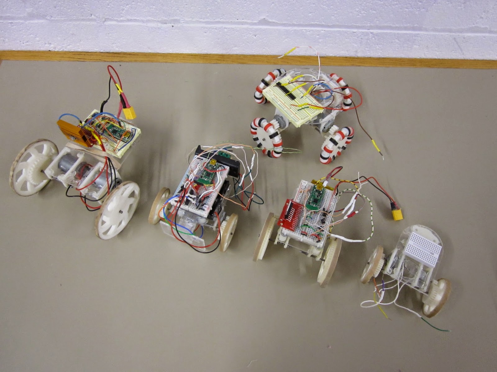
The 5 'models' of MOARbot that I've made so far. MOARbots doesn't really come in 'models' so I put that word in quotes. Overall the above robots represent my exploration of a bunch of different design elements. MOARbots as a project is just the framework/resources/suggestions one might need to pick and choose their own elements and make their own set.
When I have a need to create a set of robots though (for AI control, remote control games, whatever else), I do tend to want them to all be identical. So then I'll refine one design, and print out n many more. In that sense it has become convenient to refer to the designs as 'models.'
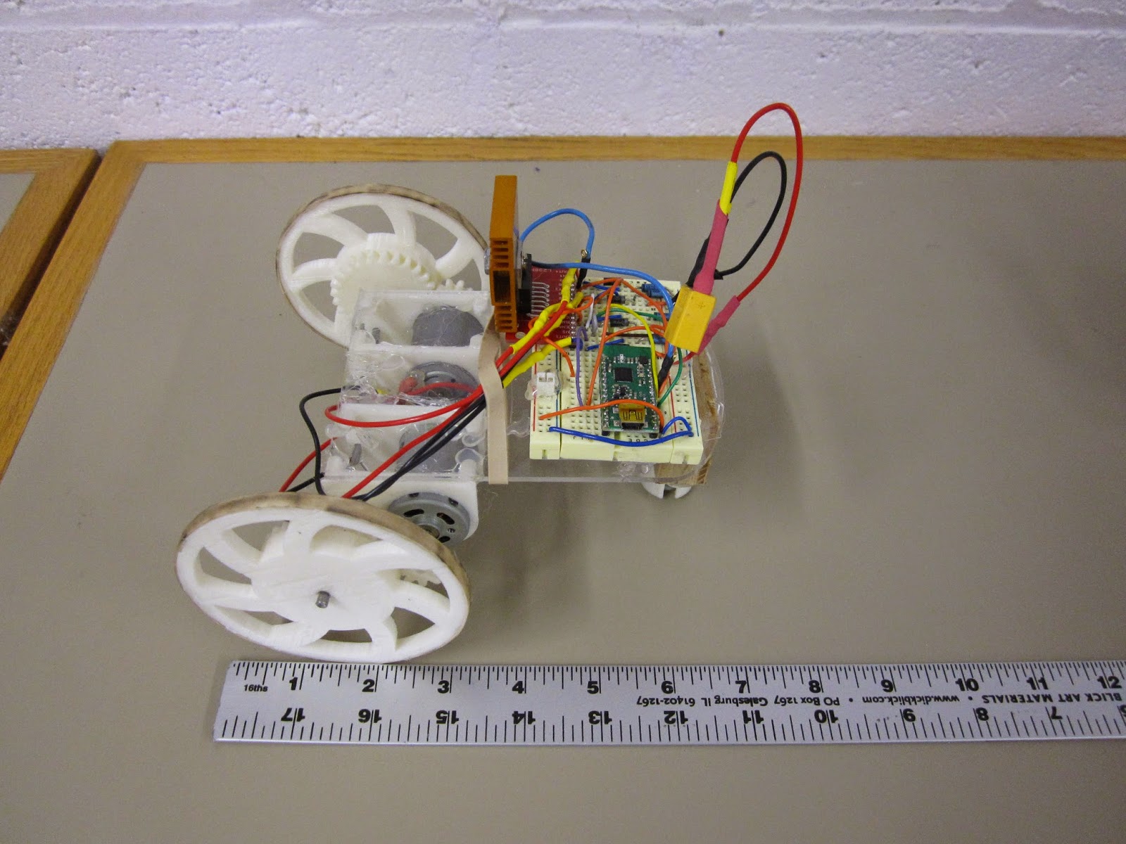
"Big Cart"
Above is the very first MOARbot. I sourced parts to make a full set of seven identical robots like this one. The motors are the very beefy RS-385SH by Mabuchi. These are geared with just a 3:1 ratio (I tried a 2:1 but with the battery weight, the thing stalled too easily). As a result it is very zippy. Notice the black marks on the rubber band tire--some Sector 67 members had fun driving this thing around quite a bit. Heat sink is definitely necessary. The stall current of each motor is 4 amps, which means that at full stall they will burn out the motor driver, which is spec'd at 4 amps total for both motor channels. The proper solution would be to use the current sensing pins to stop the motors when they draw too much current. The quick-fix solution I implemented at the time was to remind all the drivers that they should hit the brake key every time the robot ran into something.

"Omni Prototype 1"
This is the first omniwheel MOARbot prototype. It used 4 unknown motors pulled out of a bin. The omniwheel black and red 'beads' were spray coated with some products to make them more tacky, but that ultimately did not provide enough traction. A quick test showed moving a pair of motors took about 4 amps continuous current draw. The wheels slipped a lot on most surfaces as well. I came up with a much better design right after, but haven't yet finished work on that project (very very close though).

"Small Cart"
This is the smallest design so far. The motors were pulled from a bin, and only one worked. The robot was successfully able to drive in circles with 2 AA batteries (alkaline). This convinced me to try some smaller motors for similarly sized robots. If I were to go smaller than this, I'd switch away from 3D printed gears altogether and use rubber belts (like this robot that uses them with little CD drive motors). A robot like that could be built without any 3d printed parts, which would be appealing those who don't have access to 3d printing. A MOARbots project to source the parts for and build a set of those will happen most likely this year.

"Bumper Cart"
This is part of a set of 4 robots built around the FK-180SH. They are meant for playing remote controlled bumper cars, MarioKart style. The green pair of switches on the left are the target, and the acrylic panel on the left is the front of the robot. Robots race around the arena trying to hit the other robots' targets. After n hits to your target, your robot is out of the game (stops in its tracks) until the game is over and the players all agree to hit the reset button on their controllers. A pair of LEDs can be used to indicate robot 'health.' Why only 2? There are only 2 'high current' (20mA) output pins on the Wixel, and that breadboard was getting too crowded for me to start adding in some transistors.
Unfortunately the bumper carts did have one minor issue--for reasons not yet determined, the cart couldn't actually move under its own weight with the full circuit hooked up, but could move when the batteries were connected directly to the motor terminals instead. I will have to do some science to it, but I bet putting a nicer battery (2 or 3 cell lithium polymers) will fix the problem.
One cool but not completely necessary feature of the bot above and the bot below is a disconnect-able breadboard. The breadboard sits on top of three standoffs, and is held in place by magnets. The motor and battery leads are long enough to allow the breadboard to be moved around. I like this system because it means I can work on the circuit without risking pushing down too hard on the robot frame (this is mostly a fear because the diodes I bought have very thick leads and the required force to insert them into the breadboard is high).

"Independent Study Cart"
This is the cart I just finished for an independent study I'm leading at the university. The key point of this design is to use the small, cheap, and ubiquitous "130" sized motors, like this one, though you can get them cheaper on eBay if you buy in bulk from China. Knowing that these motors would be a lot less powerful than the previous ones I had used, I needed to stick as many teeth as possible on the wheel. To do that without pushing my luck on 3D printer resolution and gear alignment issues, I made the gear ring as large as possible, so now the spokes are actually on the inside of the gear. The results are good, in terms of having big safety margins on gear alignment and robot pushing force. I put a very heavy 2,200 mAh battery pack on it and it moved quite well. I will probably source significantly lighter batteries for next week's order of remaining parts.
Now I just have to source the parts for 9 more, and work out nicer battery compartments, wiring harnesses, and ID tag standoffs for this bot. Then there is also some code I need to clean up and finish up. I'm pretty excited to see this project move to the next step finally! Though I will be playing around with new omniwheel and belt-driven robots eventually, for the next window of time my focus will be entirely on the robot brains (code and algorithms) side of things.
Friday, December 26, 2014
MOARbots Bumper cars

I didn't quite get around to finishing the setup for four of the bot pictured above plus code. I had planned to get them done before I left town but holiday gift season got in the way of that. I ran into some issues at 4 AM and then realized it is 4AM and I have not a lot of time left before I have to be packed and headed to the airport. Until 'next year' then.
Monday, December 15, 2014
First set of MOARbots

The first set of MOARbots are coming together. Pictured above are the 4 cart bodies in this set. I will be assembling them before I leave for the holidays, so that Sector 67 can bring them to Saturday Science. They won't be doing anything fancy; the game is human-controlled bumper cars. The setup:
- 4 USB game controllers
- 1 transmitter wixel
- 1 receiver wixel per robot
- 6 or so red LED 'damage' indicators per robot
- Some limit switches and wire bumpers
- A modular set of acrylic arena walls, hinged with duct tape, and with holes for snapping the supports into it (to keep the robots from ramming down the wall)
The game works as follows: Control (joystick) data gets sent out from each controller to each robot (if the controllers don't switch USB slots, it ought to be possible to color code the controllers to the corresponding robots). Each robot starts with full health, so no damage indicators are on. Each time the rear bumper gets hit (note the rear is the side with the marble) all the LEDs flash and the robot is in "invulnerable" mode. After "invulnerable" mode the LEDs light up to reflect how much total damage the robot has suffered since the round started. If all the LEDs light up, the robot enters a slow blink mode and stops moving, regardless of controller input. The supervisor (the person sitting at the computer that ties this all together) can hit a key at the Python script to reset the game. This sends a reset signal to all robots, who reset their damage indicators and start anew.
This game was designed specifically to allow one way communication only (controller computer to robots only), and to not involve the webcam.
Upcoming posts are expected to be MOARbots and holiday season related. Happy Hannukah and so on.
Sunday, November 9, 2014
Mini Cart / Build Madison
Build Madison is almost over, so I get to sleep soon. I found a helper for the mini cart project, a design which will also be part of the MOARbots framework. The mini cart has immediate appeal--it can use cheaper motors and batteries, and more can fit in the arena for large multi-robot events.
Here is the mini cart alongside the regular cart.

The mini cart motors were pulled from a misc. motors bin, so they aren't exactly the same. Also, one
of them had been previously used and wasn't in good condition, so this prototype really only can turn one wheel on. The point however was to prove that it is possible to use el-cheapo small toy motors, with 3d printed gears, to move a cart.

I spent most of my time though working on an omni wheel design. I found some tackier heat shrink in large diameters that works very well for tires. Other than the tires and axles (small finishing nails), everything else is 3d printed. The triangular shape allows for two halves to fit together snugly to form the final wheel assembly. This design has very little room for error, which especially problematic given the variance on prints. A redesign should be coming soon.
One more thing: the MOARbots project has a wiki now. It is minimally populated but it will be growing A LOT especially as I get ready for a set of UW students who will be working on this project for independent study credits. I'll link it often in the future as well. https://sites.google.com/site/moarbots/home
Here is the mini cart alongside the regular cart.
The mini cart motors were pulled from a misc. motors bin, so they aren't exactly the same. Also, one
of them had been previously used and wasn't in good condition, so this prototype really only can turn one wheel on. The point however was to prove that it is possible to use el-cheapo small toy motors, with 3d printed gears, to move a cart.
I spent most of my time though working on an omni wheel design. I found some tackier heat shrink in large diameters that works very well for tires. Other than the tires and axles (small finishing nails), everything else is 3d printed. The triangular shape allows for two halves to fit together snugly to form the final wheel assembly. This design has very little room for error, which especially problematic given the variance on prints. A redesign should be coming soon.
One more thing: the MOARbots project has a wiki now. It is minimally populated but it will be growing A LOT especially as I get ready for a set of UW students who will be working on this project for independent study credits. I'll link it often in the future as well. https://sites.google.com/site/moarbots/home
Thursday, November 6, 2014
MOARbots, the ESP8266, and more omniwheels
This project finally has a title.
MOARbots: Modular, Open-Source, Affordable Robots.
Progress on MOARbots is as follows:
I learned about the ESP8266 through Hackaday and decided to purchase a few. It is a $5 WiFi chip and programmable microcontroller to boot. I haven't been through the recently translated datasheet yet, but it seems to clock at 80MHz and have 16 GPIO pins, 2 of which are broken out on the boards I purchased. It will require tons of development to be usable for MOARbots but the community is very interested in it to make Internet of Things happen at a low cost point, so I won't be alone.
I decided to make a micromini version of my omniwheel bot, based around three Pololu motors I got for free. The motors are far too expensive at $15 to be part of the framework's suggested bill of materials, but for now this is a good project to test out my designs for small 3d printed omniwheels. I'm working through some designs, and here's a render of iteration #1.

Hand forming steel wire made sense for circles, but not squares. I didn't want to take the better part of a month to build a CNC wireformer type machine, or to bother making simpler hand jigs for preset sizes or shapes, so I've rethought the design and will aim to use small finishing nails, which are cheap and widely available and don't need to be formed.
After the monthly Sector 67 meeting, a few people test drove the 2-wheeled cart. Despite the very simplistic control scheme (pre-programmed forward, left, right, stop routines), users were able to drive the cart pretty smoothly, even getting interesting drifting action at top speeds. The battery was barely drained even after a solid 20 minutes of driving, and with the addition of a heat sink the L298 motor driver was doing just fine (the heat sink is very necessary though). So this iteration of the cart is a success I think, and I will just need to buy some more L298s before I have everything I need to assemble 6 more.
MOARbots: Modular, Open-Source, Affordable Robots.
Progress on MOARbots is as follows:
I learned about the ESP8266 through Hackaday and decided to purchase a few. It is a $5 WiFi chip and programmable microcontroller to boot. I haven't been through the recently translated datasheet yet, but it seems to clock at 80MHz and have 16 GPIO pins, 2 of which are broken out on the boards I purchased. It will require tons of development to be usable for MOARbots but the community is very interested in it to make Internet of Things happen at a low cost point, so I won't be alone.
I decided to make a micromini version of my omniwheel bot, based around three Pololu motors I got for free. The motors are far too expensive at $15 to be part of the framework's suggested bill of materials, but for now this is a good project to test out my designs for small 3d printed omniwheels. I'm working through some designs, and here's a render of iteration #1.
Hand forming steel wire made sense for circles, but not squares. I didn't want to take the better part of a month to build a CNC wireformer type machine, or to bother making simpler hand jigs for preset sizes or shapes, so I've rethought the design and will aim to use small finishing nails, which are cheap and widely available and don't need to be formed.
After the monthly Sector 67 meeting, a few people test drove the 2-wheeled cart. Despite the very simplistic control scheme (pre-programmed forward, left, right, stop routines), users were able to drive the cart pretty smoothly, even getting interesting drifting action at top speeds. The battery was barely drained even after a solid 20 minutes of driving, and with the addition of a heat sink the L298 motor driver was doing just fine (the heat sink is very necessary though). So this iteration of the cart is a success I think, and I will just need to buy some more L298s before I have everything I need to assemble 6 more.
Saturday, November 1, 2014
Omniwheel Robot 1
Before giving a talk at the university, I decided it would be a good idea to...spend 20 hours straight working at Sector on a omniwheel robot prototype. I only got a half hour sleep before the talk but I guess I must have been coherent based on the response from others.
See my slides on Google Drive at this link.
Here are some photos of the omni wheel bot.

Omniwheel before assembly of beads. The wooden block is a jig for mounting the press fit gears on the motors. The vertical mount design isn't great, as weight of the robot causes the mount to flex downwards a little, which pushes the gears together more tightly, which increases friction. That will be changed in the next version.

Some of the beads before mounting. I loaded them up on a piece of wire and coated them with Plastidip (black) or Flexidip (red, pictures on the full assembly below). It is better than nothing but still not a great solution. So far my best solution has been to skip tires entirely, and run the robots on rubber mats. I'm still looking for a good tire solution though.

The fully assembled omniwheel bot. I tested it with the power supply, and it does move. It draws a bit more current than planned (5 amps or so) but I think with a little redesign I can make a lower current draw version.
I got a bin full of more stuff donated to Sector, including some really nice motors to play with. The primary goal is still ultra-low-cost stuff, so I will start looking into sourcing cheap motors. My framework will come with practical notes, including 'buying guide' type notes for some parts, as well as design files, code, and everything else.
See my slides on Google Drive at this link.
Here are some photos of the omni wheel bot.
Omniwheel before assembly of beads. The wooden block is a jig for mounting the press fit gears on the motors. The vertical mount design isn't great, as weight of the robot causes the mount to flex downwards a little, which pushes the gears together more tightly, which increases friction. That will be changed in the next version.
Some of the beads before mounting. I loaded them up on a piece of wire and coated them with Plastidip (black) or Flexidip (red, pictures on the full assembly below). It is better than nothing but still not a great solution. So far my best solution has been to skip tires entirely, and run the robots on rubber mats. I'm still looking for a good tire solution though.
The fully assembled omniwheel bot. I tested it with the power supply, and it does move. It draws a bit more current than planned (5 amps or so) but I think with a little redesign I can make a lower current draw version.
I got a bin full of more stuff donated to Sector, including some really nice motors to play with. The primary goal is still ultra-low-cost stuff, so I will start looking into sourcing cheap motors. My framework will come with practical notes, including 'buying guide' type notes for some parts, as well as design files, code, and everything else.
Tuesday, October 28, 2014
Omniwheel Prototype 2
I made a second prototype for the omniwheel. The point was to test out a few things:
- Geared hub using http://www.thingiverse.com/thing:3575 instead of Inkscape gear render
- Tighter, more closed channel for the steel wire
- Longer beads
- Tires

The knurled shaft on these smaller set of motors is pretty long, so I made the gear the full length of that. That helps keep the fit straight. I will be increasing the channel length of the other press fit gears I print from now on, so that getting them straight isn't a matter of skill with the mallet or arbor press.

The 'tires' are made from inside-outed waterproof heat shrink. The inside is tackier, but you can only inside-out small pieces at a time. The adherence isn't great unless you get the plastic just melty enough to conform to the tire without collapsing/deforming. You have to hand carve away the excess. Not a good method. I've ordered some 'silicone heat shrink' on eBay that will arrive in November; hopefully that product is different than this one. This could work great for beads with larger surface area if it came with the tacky side out.
Previously I had tried Rustoleum Flexible Rubber, but the droplets were far too big and the whole thing ended up being a globby mess. FlexiDip sprayed on nicer with a fine droplet mist but it wasn't all that rubbery. Plastidip seemed similar but a little thinner (more solvent per less payload) but this needs more testing.

Here's a picture of my second desk. HobbyKing batteries arrived today and actually seem like a good fit and weight for my cart robot design. I've already redesigned the cart gearing system, so all that remains to be done for the cart live demo is to figure out a the small gear press fit going on sideways problem, and to resize and refine the motor mounts.
Sunday, October 26, 2014
Omni Wheel Prototype
There was a plan this week to give a very small talk about my robot to a very small group of people. Then it grew into a much bigger event--university departmental computer science talk. Suffice to say, now I'm pretty amped up as well as reasonably nervous.
All this required me to think very hard about what I've been doing, what sets it apart, why it is useful, and to whom. And one thing that came out of that was me realizing that some omnidirectional wheels need to be part of my framework because some users in my talk audience will need them. Existing omnidirectional wheel designs on the web didn't fit my design principles and needs very well. So I designed the one below.


Here's a first 3d print. The beads will be spray coated with Flexible Rubber, a product sold mostly for sealing up cars and boats. They'll be loaded on a skewer and finished in bulk, which is an important point when you have this many parts to finish. This will also make it more feasible for me to spend the time to apply multiple layers, to get a good thick rubber tire on each.


Looking good--only minor design changes and a little finishing work is needed for this particular mix of the OpenSCAD parameters to be more than a demonstration prototype.
Oh, and I should mention: this wheel cost about 63 cents! That's 60 cents of 3d printed plastic and a few cents worth of steel wire. The wheel is 6cm in diameter.
All this required me to think very hard about what I've been doing, what sets it apart, why it is useful, and to whom. And one thing that came out of that was me realizing that some omnidirectional wheels need to be part of my framework because some users in my talk audience will need them. Existing omnidirectional wheel designs on the web didn't fit my design principles and needs very well. So I designed the one below.
With beads assembled
Frame only
The key things about this design are as follows:
- It only requires one piece of hardware--some wire. I have some 16 or so gauge steel wire, but you can pick anything that feels right to you for your size of wheel, and input those dimensions into the OpenSCAD file.
- Everything can be changed easily in the OpenSCAD file. Number of beads, shape and size of the bead, gauge of the wire, etc. This will be more true after some cleanup on my part, when I get it ready for release on Thingiverse and elsewhere.
- Everything besides the steel wire is 3d printed. It is often easier to 3d print beads than to find beads that fit the wire closely.
- The 3d print does not have to be split in two in order to print. Assembly is simple and doesn't require any 'finicky steps.'
- This is because the channel for the wire is opened up, specifically at the point where printing more of the channel would break the 45 degree rule of thumb for 3d printing. It has a snap-in kind of feel.
- Hot glue can be used optionally to help tack down the wire where needed.
- The wheel hub/gear module will be added on top in the final version without any fuss. To illustrate how this can be a problem with other designs, consider the version where an enclosed channel is created by printing the wheel in halves split along the central X-Y plane of the wheel. In order to not break the 45 degree rule, you have to print the inside faces up. In order to print the wheel hub though, you need at least one outside face up. (My solution in that case would have been a triangular channel).
I'd like to come up with a few more variations on this, and maybe tackle a similarly informed design for Mecanum wheels or two-layered omni wheels.

Here's a first 3d print. The beads will be spray coated with Flexible Rubber, a product sold mostly for sealing up cars and boats. They'll be loaded on a skewer and finished in bulk, which is an important point when you have this many parts to finish. This will also make it more feasible for me to spend the time to apply multiple layers, to get a good thick rubber tire on each.
Looking good--only minor design changes and a little finishing work is needed for this particular mix of the OpenSCAD parameters to be more than a demonstration prototype.
Oh, and I should mention: this wheel cost about 63 cents! That's 60 cents of 3d printed plastic and a few cents worth of steel wire. The wheel is 6cm in diameter.
Thursday, October 23, 2014
Robot Cart Progress -- It Drives!

First assembled prototype. Preliminary tests show that (a) it is capable of driving smoothly and (b) it doesn't draw too much current for the L298 motor driver. Spent yesterday evening hunting down flyback diodes at Sector and I even found two additional L298s, as well as a handful of extra large breadboard-compatible tactile switches (pictured left, in the background).
The Wixel code for the transmitter is done. Next up is integrating the PWM code to the receiver modules, and creating easy to use skeleton code for competition participants to come in and edit.
I still need to get additional batteries, a suitable USB camera with a good wide angle of view and OpenCV compatible drivers, and a few other parts. So far so good though.
Edit: Minor Setbacks
I bought these batteries from Adafruit and these batteries from Sparkfun. The Sparkfun batteries provide enough current to get the cart moving, but if it hits any obstacle and stalls, this triggers the overcurrent protection. Toggling the power on and off resets this protection. The Adafruit batteries can't even run the motors unloaded (wheels not in contact with the ground). They twitch, then die out (presumably, overcurrent protection). This is a shame, because I purchased them on the assumption that they would provide a maximum continuous 2C discharge rate, which they aren't, as far as I can tell. The datasheet seems to say that (bad formatting on it makes it hard to read).
In any case, Sparkfun's comment system and tendency to better document products on the page makes me feel a lot better about purchasing from them when they have the stock I want. Unfortunately neither battery will quite do for my needs, so I need to go back and rethink this.
Also, I wasn't able for whatever reason to get the wixel-pwm library by dpark83 working for me. It isn't particularly well commented which makes it difficult to use. I did find this simpler code, which works well enough for me to use instead.
Since the price for these robots is already quite high, I'm going to try and re-use some parts around Sector. Namely, a bin of old cheap lithium ion batteries without any protection circuits, and a bunch of scrapped prototypes for a battery board that has no documentation, but a ton of features (presumably). Or, in the interest of time, skip the reverse-engineering on the battery boards, and just triple check to make my circuits don't look too explode-y, and go protection-less. So far I haven't made any really serious mistakes with my wiring prototypes...
Sunday, October 5, 2014
Robot platform in progress
Entire post got deleted while I tried to fix the alignment between the photos shown below. The Blogger WYSIWYG (what you see is what you get) editor is terrible for images, column layouts, etc. In short: I've been working on a lot of things recently, but haven't posted because posting takes time and effort and you need to get good photos of stuff and find a good stopping off point on those projects that never end.
The biggest thing I'm working on now is a robot platform that will be open source. The brain will be the Wixel and the cost will probably be in the $50-$60 to build it yourself. The gear/wheel/mounts prototype are shown below. To give you a sense of scale, the wheels are 9cm diameter and in the assembly shown below, the distance from the wheel to the motor terminals is about 7cm. The first goal for these will be to build seven of them myself and use them to run some fun programming competition aimed at adults/experienced programmers at Sector 67. Past that, I'll probably use these with an Arduino (in addition to, not instead of the Wixel) if I teach a robotics class this summer again.


The biggest thing I'm working on now is a robot platform that will be open source. The brain will be the Wixel and the cost will probably be in the $50-$60 to build it yourself. The gear/wheel/mounts prototype are shown below. To give you a sense of scale, the wheels are 9cm diameter and in the assembly shown below, the distance from the wheel to the motor terminals is about 7cm. The first goal for these will be to build seven of them myself and use them to run some fun programming competition aimed at adults/experienced programmers at Sector 67. Past that, I'll probably use these with an Arduino (in addition to, not instead of the Wixel) if I teach a robotics class this summer again.
Sunday, July 27, 2014
July Robotics Class Weeks 2 and 3

A bunch of motors from my late night eBay hunts

3D printed parts held together with popsicle sticks and hot glue; worked very well.

Neater gearbox designed by the TA. Very nice design. Short print times.

Robots coming together.
We ended up spending more of our time focusing on programming, which was important to cover.
Soon I finally begin my journey home. I plan to hibernate and cuddle with my cat for at least a week. Below is said cat.

Subscribe to:
Posts (Atom)