Showing posts with label electronics. Show all posts

Wednesday, June 7, 2017

Indoors Navigation Robot ("Driving Drawers") Post 1

[Foreword: you may notice the fonts are mismatched in this post. Or maybe you noticed that the images in all the posts in this blog, when viewed on a larger screen (as opposed to a small mobile device screen), are placed haphazardly within the body of the post. This is because Blogger leaves much to be desired when it comes to the WYSIWYG post editor. In part because WYS ("What you see") is not always WYG ("what you get") in the context of Blogger's post editor, but also because there are very limited options for aesthetic image layouts in the body of a post. I am planning a Jekyll based webpage for this blog in the general future that will fix these problems. Until then, this is a cheap and easy way to make sure I keep a blog at all.]


I had an idea for a chest of drawers that would drive to my location in a space (assumes no stairs).

Here's the first part of my progress on that project.

Physical Build

I started by dissecting my collection of Roombas and taking the wheels from two different models and hot gluing them, along with some support material, to the base of a plastic chest of drawers.


I purchased a Raspberry Pi 3 and a PiCam, and while I waited I put together a 3D pan-tilt design from Thingiverse. I'll provide a link (link to thing), but keep in mind I do not recommend this design. Unless your 3D printer is very precise, you'll have to do quite a bit of filing and sanding to get it to go together. The pan servo will absorb all the impact whenever it hits something, and will fail (mine did). If you can find a ring of the right thickness and diameter to stick in between the orange disc and blue plate in the photo, the problem is mitigated (I used a bearing I found in a bin--way overkill as it isn't even acting as a bearing--but a quicker solution than cutting my own ring on the lathe).


Not entirely certain of the layout I wanted, I just taped everything in place with masking tape. The battery is stored underneath, in the topmost drawer of the robot. It's a 30,000 mAh battery I bought for use with my smart phone. It has a port that will source 2.5A, which is needed by the Raspberry Pi. I paid about $75 for this model; you should be able to find comparable batteries by other brands if that one is not available (sometimes, when an item is out of stock, a few vendors will offer it for an inflated price, so beware. The price on Amazon for this model was briefly $399 before dropping to $69.99 again). 
I pulled the Arduino Mega out of a project I'm not working on at the moment, though it is of course overkill for this application. I wasn't sure how many sensors and actuators I wanted on board, so this 54 I/O pin Arduino allows for quite a bit of room to grow the project. The Raspberry Pi 3 itself only has one PWM enabled pin available to me, so the Arduino is convenient for handling all the low level stuff. It talks to the Raspberry Pi over the USB. The micro servos are powered from the Arduino Mega which are in turned powered off the Raspberry Pi. The micro servos stall current is low enough for this to be possible with the Arduino Mega.


 The Roomba wheel motors are safe at 12 volts (the Roomba battery voltage), so I put another battery in the system just for them. The battery is a 3 cell Lithium Polymer battery, which measures in at roughly 11.1 volts when the battery needs to be recharged and 12.6V when the battery is fully charged. The motor drivers are L298 chips on those red-colored Sparkfun breakout boards, with the heatsinks mounted to them.


So at this point the robot was driving, but only in a straight line. Turns would drag at least one wheel and make a terrible noise. Only very slight turns worked. This was fairly predictable, but trying to make it work anyway was very much in keeping with my glue-and-tape, then iterate style of prototyping. Jesse helped me put together a steering mechanism in a very short amount of time. It worked, so that evening I took the robot out for an inaugural journey around Sector67, using it as a sort of telepresence robot as I controlled it from my desk.


Then I broke the steering mechanism gearmotor by switching it back and forth too fast when I got stuck in a corner. The gear before the final output shaft broke into a bunch of tiny pieces.


I replaced it with the gearmotor in the image above on the right that has the partly blue casing. Now that I had a working robot again, it was time to work on the high level path planning and code. I'll put that in the next post.


Tuesday, March 7, 2017

Talking Calipers 2

Preface: Voting on a contest I submitted this to is open right now. You can vote once a day through this link. http://review.wizehive.com/voting/view/infypublic2017/47311/4496312/0

Before going all in on the research for my minimal-cost minimal-footprint all on one custom PCB version of the Talking Calipers, I went through my bin of parts and made one more with just what I had already available. It uses:


The video demonstrates that the reading is taken when the button is pressed, so the display can potentially change to reflect that the measurement has changed since the reading began being spoken aloud. The button is a limit switch super glued next to the thumb wheel.

It was a useful learning experience to build, and it was good to have it done quickly for demos and such, but in the end I built something very, very similar to the Adafruit Wave shield (https://www.adafruit.com/product/94) but slightly more expensive.

Feature list (all were tested on the breadboard, though some haven't yet migrated to the somewhat portable prototype):
  • Rechargeable battery on board, recharges via USB
  • Separate amp with lower gain for headphones for hearing safety
  • Headphone detection for automatic headphone/speaker output switching
  • SD card for easy file loading--can be made to work in any language by switching out files
  • Relay mutes headphones to reduce pop
  • Sleep mode that wake up on request for a reading, for longer battery life
Features not yet added:
  • Filter to get rid of a hum caused whenever the SD card is read
  • Low battery indicator (through sound or vibration ideally!) (though thanks to a circuit built in to the battery header, it will turn itself off to protect from under-voltage to the battery)
  • Inches mode protocol is different and currently reads off incorrectly
  • Audio files and code support for reading numbers more naturally (currently reads off each digit separately)
  • Change sleep mode to trigger only if the readings are constant and the button is not pressed for a certain time interval (right now just based on button)
I actually recorded my voice for this project since I couldn't find everything I wanted online. I used http://www.audacityteam.org/ to create the files and then used http://sox.sourceforge.net/ to make sure the files were 44.1kHz sampling rate and 16 bit sample size and then volume adjusted to a max volume that did not clip. (Note: the wav shield played most any wav files I could find fine, but the Teensy audio library was picky about the settings, necessitating use of the sox tool).

I estimate the battery life at about 10 hours of use (assuming it never enters sleep mode). The main power switch does lose the zeroing, but is convenient to have (out of the box, these calipers draw enough current to drain the coin cell in half a year to a year, unless the battery is removed). Auto-entering sleep mode when the user is away helps extend the battery life even more.

Tuesday, February 14, 2017

Talking Calipers 1

At a recent Sector67 monthly meeting, a member who teaches at a school for the blind and visually impaired mentioned a need for talking calipers. They are hard to find for sale and they typically cost in the realm of $250, though if you have a link to something significantly cheaper please let me know. My overall goal is to design a cheap little add-on that slots on to standard calipers that have a serial output already. This post is about the first step: a quick talking calipers proof of concept. Here's a picture of the working setup. See bottom of post for a video of the setup in action.


Here's what's in the photo. Everything came from either my collection of prototyping stuff, or from the collection of a fellow Sector member who took interest in this project.

If you add up the total cost of the items listed above, it comes out to about $85...so already cheaper than the $250 price point. (I'm aiming to get the total cost down a lot further than that though).

Here's how it all works together. The calipers are bumped up from their usual 1.5 volt voltage from the coin cell, to a 1.9 volt supply from the breadboard power supply. This makes it so that the logic level converter works with the signal from the calipers (because the minimum signal it will support is 1.8 volts, so 1.5 is too low). The signal from the calipers is easy to access; there's a port on the calipers accessible by a removable plastic cover. On the other end of the logic level converter we have the Arduino at 5 volts.

The wave shield comes with it's own example code. The calipers communication protocol has already been reversed engineering by a number of folks online; I got my code snippet from http://nut-bolt.nl/2012/reading-digital-calipers-with-an-arduino/.

The main challenge here is that the Wave shield uses all the external interrupt pins on the Arduino. I needed to use a different kind of interrupt. After a brief read through the forums and the datasheet for the Atmega328P, I decided to use the analog comparator. Comparing against some code snippets made it a fairly easy job to set all the registers I wanted to the values I needed. I used the internal bandgap reference as the positive input to the comparator and my calipers CLOCK signal as the negative input. Then I set the interrupt to trigger on rising output edges. [Noting that the positive input to the comparator, Atmega pin AIN0, refers to Arduino pin D6, and the negative input to the comparator, Atmega pin AIN7, refers to Arduino pin D7.]

The code for this project is available here.

Here's the video:


Next up I'll tackle building a prototype of a cheap and portable version.

Saturday, September 19, 2015

Current Limiter Project Wrap-Up

Four years ago I made my first printed circuit board using EagleCAD and purchased a few units using BatchPCB. It was a version of this current limiting circuit with R5 as a potentiometer, which lets me modify the cutoff current. By the time the boards arrived I probably had exams or something, and so the project was forgotten.

Today I was trying to clean my desk, but I found the boards and got distracted. I scavenged around Sector67 for parts (making backwards progress on the desk-cleaning situation) and populated the board.


When the output draws under some current limit (can be modified by the potentiometer), the green LED is on. When the output would draw more than that limit, the red light turns on, and the output current is limited to what flows through the red LED and resistor in series with it. The concept and operation is described in detail at the Instructables page of the source for this project: http://www.instructables.com/id/PC-Power-12-V-Current-Limiter/

I made the traces thinner than I would have liked. It was my first time getting a PCB made and I didn't realize that I had forgotten to set the trace width until it was too late. The default trace width is probably fine here anyway. It feels good to finally wrap up this project. I could go further with it (compute some values, measure some values, stress test the board, refine the design) but there are hundreds of other projects that will probably take priority.

Thursday, October 23, 2014

Robot Cart Progress -- It Drives!


First assembled prototype. Preliminary tests show that (a) it is capable of driving smoothly and (b) it doesn't draw too much current for the L298 motor driver. Spent yesterday evening hunting down flyback diodes at Sector and I even found two additional L298s, as well as a handful of extra large breadboard-compatible tactile switches (pictured left, in the background).

The Wixel code for the transmitter is done. Next up is integrating the PWM code to the receiver modules, and creating easy to use skeleton code for competition participants to come in and edit.

I still need to get additional batteries, a suitable USB camera with a good wide angle of view and OpenCV compatible drivers, and a few other parts. So far so good though.

Edit: Minor Setbacks
I bought these batteries from Adafruit and these batteries from Sparkfun. The Sparkfun batteries provide enough current to get the cart moving, but if it hits any obstacle and stalls, this triggers the overcurrent protection. Toggling the power on and off resets this protection. The Adafruit batteries can't even run the motors unloaded (wheels not in contact with the ground). They twitch, then die out (presumably, overcurrent protection). This is a shame, because I purchased them on the assumption that they would provide a maximum continuous 2C discharge rate, which they aren't, as far as I can tell. The datasheet seems to say that (bad formatting on it makes it hard to read).

In any case, Sparkfun's comment system and tendency to better document products on the page makes me feel a lot better about purchasing from them when they have the stock I want. Unfortunately neither battery will quite do for my needs, so I need to go back and rethink this.

Also, I wasn't able for whatever reason to get the wixel-pwm library by dpark83 working for me. It isn't particularly well commented which makes it difficult to use. I did find this simpler code, which works well enough for me to use instead.

Since the price for these robots is already quite high, I'm going to try and re-use some parts around Sector. Namely, a bin of old cheap lithium ion batteries without any protection circuits, and a bunch of scrapped prototypes for a battery board that has no documentation, but a ton of features (presumably). Or, in the interest of time, skip the reverse-engineering on the battery boards, and just triple check to make my circuits don't look too explode-y, and go protection-less. So far I haven't made any really serious mistakes with my wiring prototypes...

Friday, July 11, 2014

July Robotics Class Week 1

Photo essay for week 1 of the July robotics class I'm teaching.

A simple H-bridge with switches and LEDs.


Omni-wheel proof of concept; 3d printed plate that fits on a motor shaft.

Printrbot has been printing lots of stuff.

Stickers, buttons, and temporary tattoos for prizes.

Robots under construction.

Another partially finished robot.

Tuesday, November 1, 2011

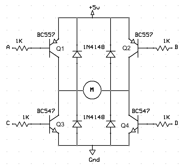
A note about H-bridges

If you are a n00b like I was back in freshman year, or just forgetful (like I am now) you might want to take note before you burn out a bunch of transistors.

At some point you may realize you only need 2 inputs to control your h-bridge. You will tie the left hand inputs (base of Q1,Q3) together, and the right hand inputs (base of Q2, Q4) together.


Likely, burning transistors will at some point result, because the inputs will be left floating. For me, I accidentally pulled out the input wires.

"The important thing is you cannot leave any of the terminals AC and BD float. Let’s look at the AC terminal in more detail. Since A and C are tied together, and if it is left float then there will be a path for current through the collector of Q1, through its base, through the base of Q3, through its emitter to the ground. So, Q1 and Q3 are on resulting a short circuit. So, you must be careful if you are thinking about reducing the control pins by tying A with C and B with D. You just can’t leave the tied terminals open or float. They should be either grounded or pulled high."

Read more here: DC Motor Interfacing to PIC Micro. Scroll down to the "Important Note."

Friday, April 23, 2010

FM Transmitter - in Stereo!

A long time back I built a super-simple FM transmitter that worked off 1.5 volts. I used this schematic which you can find all over the internet (this image is from a pdf of a book called "101 Spy Gadgets for the Evil Genius"). It worked well and was easy to build.


Understanding nothing about how it worked, I attempted to plug in my iPod in place of the microphone. While I could recognize the received signal as definitely the same one I was sending, it was very strongly garbled. The iPod transmits a signal with some power, and it was enough so that when I unplugged the AA battery the thing still transmitted. This probably screwed up its operation a bit.

A few weeks ago my EE200 (Intro to Signal Processing) professor mentioned that we could do an extra credit project. The project could be just about anything so long as he approved it. I immediately decided to return to the FM Transmitter project. I quickly found this page that describes how to build one without using a special IC designed for stereo FM transmission. It is relatively simple to build and the page describes how it works in detail.


Here is a photo of it assembled on a breadboard. I tested it by listening to the output through my roommate's portable radio. Once I got everything right (see the below listed quirks) the sound was of very nice quality! It is powered from the wall via an adjustable breadboard power supply from LadyAda of Adafruit Industries.

Quirks:
  • There's a lot of background noise. The website makes a few suggestions about how to improve it, some of which I may try in the future. Then again, I don't think it will be so noticeable when listening to it through my ancient and terrible car radio.
  • Every so often, when I touch something (even the iPod's metal case!) I hear I high-pitched, very clear tone. No clue what causes that. It isn't consistently replicable...
  • Finicky tuning. The signal is only really clear if you tune it just right. If you don't you can hear the signal but it starts to get badly distorted and very noisy.
  • Clarity of signal is best if the iPod is set to about 1/4 volume and the radio is adjusted to liking. I got weird distortion above that.

After this project has been presented I plan to pack it all onto a piece of Veroboard and into a nice enclosure. I will make it either battery powered or car-outlet powered with the addition of a 5v limiter. I will fix the tuning issues (touching the inductor/variable capacitor or getting anywhere near them changes the frequency to which the transmitter is tuned, which means I will have to isolate these parts while still having some mechanism for turning them in place).

While buying a transmitter is cheaper and probably results in better sound quality, it just isn't as cool as building one myself. I'm so excited about this project that for the last hour or so I've been listening to my iPod through the radio even though I could technically play all my music directly from my laptop.

Monday, January 25, 2010

USBTiny ISP, Radio Transmitter, Simon's Game

The USBTinyISP kit I ordered from Adafruit arrived today, and I wasted no time at all in putting it together. The final product looks like this:


Due to a few rounds of soldering/desoldering of the ISP pins for Simon's Game the PCB was peeling, and I was pretty worried that I would not be able to get it [Simon's Game] to work. So I was very relieved (and also ridiculously excited) when avrdude wrote to the board without complaining.


The first few times I played it would occasionally freeze up and play a high pitched sound continuously. It seems to have been a fluke though because I can't recreate it now. The only other problem is with single button presses that registers as two presses, but I can always reprogram the microcontroller to ignore a signal if it follows the one before it too closely.

Last night Allen and I built a FM radio transmitter, similar to those used as iPod adaptors for car trips. It has a good range for a device that works off a single AA battery. We're thinking of designing our own tiny receiver/transmitter pairs for use as walkie talkies.

The radio transmitter is only a prototype on a breadboard now and doesn't make for a very interesting picture, so here's a photo of my workstation after I've cleaned up:


Also, I found the old hacking game website Starfleet Academy and a different one I wasn't familiar with called try2hack. I really enjoy doing these. If you're new to online hacking games and want to try one but don't know anything at all about how to start approaching them, I'd recommend figuring out how to use your browser to see the HTML code for any given web page. That's the basic step that will let you start figuring out each level.

Saturday, December 19, 2009

Drawdio

To celebrate the end of finals and the end of fall semester, I felt like a quick and easy electronics project was in order. The Drawdio delivered. It took about five minutes to assemble the easy-to-find parts, and the result promises to amuse me for hours, at the least.


I prototyped it on a breadboard and will fit it onto a pencil tomorrow. I used the Adafruit design but without buying the PCB or the kit, these are not necessary. Radioshack and a Veroboard/Stripboard will do just fine.

Again, everything you need to know about the Drawdio is explained here.

And yes, I am the kind of person who, when first introduced to the theremin, thought it was the coolest thing ever and dreamed of getting one and playing the Legend Of Zelda theme on it. Ergo, I love the Drawdio, and I will soon be trying to draw a keyboard with the right resistivity between the points so I can play music on an instrument I drew on paper. TOTALLY AWESOME

Now that I have tons of time, I think I'll be getting back to the rest of that Pacman assignment from last post.

Thursday, July 16, 2009

Automatic Dark Detecting Joule Thief Nighlight

I was shopping at Wacko's for toys to fit electronics into, and the Munny was pretty much the only thing I found that was big enough, hollow enough, cheap enough, and made of vinyl (pliable enough). For about $10 it made an affordable and fashionable chassis for this project.

After decorating it with various electronic components, I set to work on the insides.


Part 1: The dark detecting circuit. I found these schematics on Watson's Blog, but since I couldn't find the mosfet required for Watson's modified circuit, I used the EvilMadScientist original circuit. I added one more LED in parallel (total 2). I also replaced the 1kohm resistor for two resistors totaling ~30kohm, which decreased the sensitivity. A note: this also seemed to dull the maximum brightness the LEDs can attain, but at 30kohm they still shine pretty bright.

Part 2: The Supercharged Joule Thief. I used my favorite schematic (Fig. 2, w/o the button cell) also from Watson's Blog for this one.

Part 3: putting it together (EDIT): I just kind of mashed the two circuits together. It was guesswork, and while it worked, I'm pretty sure it didn't work well. Mainly, I was hoping to find a design that would be very efficient so that I could leave it on all the time, and in this sense it did not work at all (the battery only lasted a few days). So I guess just have to read my physics book, do some calculations, and redesign...

I had planned to do this with the standard AA battery, but the holder wasn't going to fit in the doll very nicely. So I swapped that for an AAA battery, which works just fine as well. I improvised my own holder by cutting a piece of tube from the center of a CD holder (the kind blank CDs come on, when you buy them in gigantic packs at costco). I improved terminals at the top and bottom with aluminum foil, and then stuck the whole tube into Munny's lower torso (his head pops on and off for easy battery replacement). I'm not entirely happy with it, but it is easy to replace and if I ever find a thin single AAA battery holder, I will swap it in.

Result: in daylight (even indoors, with closed shutters) the light is off. And at night:

Thursday, July 9, 2009

Brushbot

I'm still enamored with the Joule thief idea, but more importantly, I have a goal: to get the most out of this bucket of old batteries (pictured below) before the batteries start to leak (or before I amass any more of them).


I'm not too fond of flashlights anymore, because I can't make them small enough to be keyring friendly, and because most people don't use flashlights that frequently. So I've switched to mini LED trees (mini tree, not mini LED), like this one I gave to my sister to liven up her dorm room desk:


But making LED trees can get boring, so enter the brushbot:


The brushbot isn't a very good roomba substitute. He's useless on rugs and he tends to just circle in one place. But he could be useful in polishing stuff, and besides, he makes a mean zen garden.


By the way, the brushbot does NOT run on wheels! He just vibrates his way across a surface, like a cell phone or rumble-equipped controller left on a table. Brushbot is made of two red LEDs, a motor with an asymmetric thingamabob attached to it, and a joule thief per this schematic (Fig. 2) from "Waston's eBlog."

Saturday, June 20, 2009

LED Tree


It isn't too bright (I used a 4 AA battery supply, so about 6V, and there are 52 LEDs in parallel on the tree), but it does provide a nice ambient kind of glow to a dark room (you almost can't see it in the light). That was the goal, I guess, and I put in a Joule thief circuit in hopes that it would extend the battery life a little, though I'm not feeling up to actually testing it.

Though this one was a bit of a pain, I have some ideas on how to improve on the design and I'm definitely going to make some more similar LED artstuffs in the future.

EDIT: So like I thought, it is pretty much for certain that the Joule thief is kind of silly in this circuit, because it doesn't seem to actually be doing anything useful. Also, the lifetime on the lamp isn't too great. It'll last through a whole night, I guess, but come up kind of dim in the morning. If you turn it off for a bit it gets brighter again, but near the end of the battery life that extra brightness doesn't last long. One day in the future, when I have completed a number of EE and physics courses and have hopefully gained some understanding of what it is I'm trying to do, I will redesign the guts of this tree.

Thursday, June 11, 2009

Joule Thief + Another Fridge Magnet

So the main, big project I'm working on now is getting kind of frustrating, and I thought I'd take a break tonight with a few quick projects.

I started with a empty box of chocolates from Trader Joe's. It had an adorable design with a porthole in the middle, and I had to use it somehow. Using a dremel I cut the bottom of the box off, and then I glued on three magnets with super glue. The top fits snugly onto the bottom, so all that was left was to find a picture for my picture frame.


Big Daddy character copyright 2k, of course.

Anyhow, since that project had just about two steps, I needed something else to do. Half an hour on instructables (an amazing site, by the way) reminded me that I had always wanted to build a Joule Thief. It is a remarkably simple project, but I still feel proud of myself.


You basically need an NPN transistor (2N3904), an LED, an old battery, a small toroid magnet, a 1kohm resistor, and thin wire. Optionally, you'll want a AA battery holder and a switch. I already had everything except the toroid.

Of course, the Radioshack store people had no idea what I was talking about when I asked for the toroidal magnet thing, so I found the part number myself. If you have to go to Radioshack and pay their inflated prices, here it is. Note you can probably try to use the 273-108 if you can't find the 273-109 in stock.

The 2 AA battery case leaves plenty of room to house the battery and the innards (in the second battery's place). It is a little black and boxy, but you can decorate it with stickers and such.

-Shira

Saturday, February 28, 2009

Feedback Machine + Reading Magnetic fields

Allen was the brains behind this. We used this schematic and he added in an LED and a rheostat to control gain.


Because it has a magnet in it, the speaker conveniently sticks to the altoids tin while still being detachable. The indicator LED is inside (the red dot on the right).

The point of building this pocket amplifier was to listen to the output of a coil of thin gauge wire--ie, read magnetic fields. However, we built it kind of messily and it turned out to be more of a feedback machine. I did get some interesting results though, especially when holding it up to chargers and then unplugging them.

Later on, I found the following bit of treasure in a dumpster near the old Lucas building. It is a piece of old recording equipment, basically a magnetic tape reader attached to a 1/4" audio plug. I plugged it into my real amplifier, and achieved my original goal with much less extra noise.


I imagine it as a stethoscope for my computer.

Sunday, February 22, 2009

Solar Powered iPod Redux

Here is an older project of mine to set this blog in motion.


Summary of parts:
I am using the little printed circuit board that came with the garden light that came with the solar panel. It does what I need and was easy to hook up so I haven't bothered diagramming it. If I was a more dedicated person, I'd figure out the layout and share it online. But, I am not!

New iPods are more finicky than old iPods! Older iPods only need the input and the ground (+ and -, red and black, whatever). Many (storebought or homemade) cheap/old chargers work like this. They won't charge your new iPods though! New iPods (like my 80GB Classic) need their data lines hooked up too (the green and white ones if your cable is colored according to standards). Follow this diagram (which I found here).


Technically, I am supposed to use a 5v regulator (like the 7805). But when I hooked it up, I was only getting like 4.18v to my iPod across the + and - terminals. I took it out and I'm getting 5.09v (.09 too many) but I don't think my iPod is hurting too badly.

Other notes:
Rechargeable (as opposed to regular) AA batteries are 1.2v, not 1.5v. Four of those arranged in series supposedly make 4.8v, but I get 5.09 volts out for some reason. Works for me though!

Anyway guys I think this is pretty sweet! Sunlight streams into my device and at the other end I hear music.

Epilogue: Later, while attempting to add an LED to the mix, two wires touched and I shorted something on the circuit board by mistake, having once again forgotten to remove the batteries before soldering. I believe it was either the PNP or NPN transistor...but when I looked into replacing them I realized the circuit board had taken too much abuse already, and was falling apart. I plan to figure out (or find somebody who can figure out) how it worked and build a replacement someday.