the wire loop game
(there was a video here; I'll try to put it back later. It got lost when I tried to fix the formatting. Blogger seems kind of dead. I should migrate this blog...)

(I forgot about this one! I did half the write-up when I wrapped up the project in 2018 and then forgot entirely about it. here it is now...)
This is an implementation of https://en.wikipedia.org/wiki/Wire_loop_game
Game behavior:
To start the game, the player touches the loop to the wire on the starting post (in red). This starts the counter over from zero, and counting starts when the loop comes off the starting post.
If the player touches the loop to the track, the player loses (indicated by red light and buzzer) and the timer shows the final time when the game was lost.
If the player touches the loop to the wire on the goal post (in blue) then the player wins (indicated by green light and for now, buzzer [but was intended to be replaced with a simple sequence of tones]) and the timer shows the final time of when the game was won.
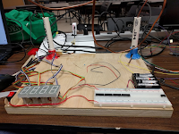
The physical platform
Goal posts modeled in OpenSCAD

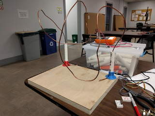
Attached with hot glue, PVC pipe to a wooden platform. The wire is some salvaged coaxial stuff, if I recall. It is pretty rigid but can be deformed into new shapes for a different difficulty of game.
The counter and timer
I picked out some 1” tall seven segment displays and the CD4017BE which is both a counter and a seven segment driver. I used rainbow colored ribbon cable and female 0.1” pitch header pins to create connectors that were easy to trace, since there are so many connections needed.
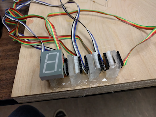
I decided on 4 seven segment displays: 100 milliseconds, 1 second, 10 seconds, and 100 seconds. The 100 seconds is a little extraneous, since most people don’t take that long to either fail or win the game. The CD4017BE units have a carry out pin, so I only need to feed a 100ms clock to the first unit, and then put the carry out of that unit to the clock on the next unit, and so on.
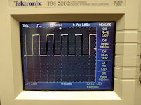
For the 100ms clock I debated using a high frequency crystal and dividing it, to achieve good precision in timing. But I ended up going with a 555 timer. The circuit is built as a 50% duty cycle oscillator as seen in this tutorial.
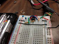
The ~100 millisecond clock
I also made the choice here to use a 4 cell AA battery pack, which for alkaline batteries maxes out at about 6V for fresh batteries. I was sticking with a theme of using older logic ICs that were rated for 5-15V or wider ranges. A couple more modern devices I looked at briefly had maximum recommended voltages in the range of 4.5-5.5V, so this eliminated some options.
I added a trimmer potentiometer to help dial in the frequency, which will drift with things like ambient temperature. I had fun dialing it in to 100ms though it definitely drifted as I added to the output of the circuit.
The state machine
Here I took a moment to design the state machine for the system. I knew I wanted indicator lights and indication sounds for both winning and losing. I came up with the following list of states: Idle, Active, Fail, Win. I simplified this further into two categories; game active, and game inactive.
When the game has started, the timer should count up. When the game is over for whatever reason (win or lose), the timer should stop counting up and flash the numbers on and off to make it obvious to the user. I dropped the idea of Idle state as optional and not worth implementing, because as I imagined it originally, it was only used between the time the user turns on the system and the time the game first starts.
I wanted a press for either the fail switch or the win switch to end the game, so I added a CD4071BE.
I picked a JK flip flop to implement this very simple state machine. I found we only had one type, the CD4027BE. There are two JK flip flops on each chip.
[diagram that i didn't make but did describe as follows: J goes to Win OR Fail. K goes to Start Switch. Reset goes to Start Switch. Qbar goes to Game Active] [I also noted to myself to check this is correct]
When the start switch is touched, the game state is reset to active. However since the reset also is tied to the reset of the seven segment drivers, holding the start switch closed will keep the timer held at 000.0 seconds. When the start switch is removed, the game is active. When the user hits either the fail or win switch, the game goes back to inactive. The clock for the JK flip flop is another 555 timer set to a 1 millisecond period, because that was fast enough that I could not purposefully brush the wand against the copper wire fast enough to make it not register.
At this point, I created the other parts of the game ‘switch.’ The main maze/course is the ‘fail’ terminal. A small loop of wire on the start post is the ‘start’ terminal. Another small loop of wire on the ending post is the ‘win’ terminal. Finally there is the loop of wire with a handle that the user manipulates. To successfully solder to the copper wire required a lot of heat (I used a Metcal and took my time) and a lot of flux.
At this point the game was playable and people enjoyed it.
Unfinished notes
At this point the writeup is a little sparse...It appears that I was not diligently keeping notes as I worked and was having to go back and recreate my thinking... here it is unedited anyway:
[remind yourself to look into what that second jk flip flop was used for]The fail buzzer
The state machine must know whether it is inactive because it failed or because it won
Fun with BJT transistors, describe that here
Turning on and off the dot with the other segmentsTrying to make sure that at power on the segments don’t bounce up one clock, and that hte green light does not default on, involves caps, but as i added more circuitry sometimes i needed to change those.
Differentiating input for the 555 timer controlling the note length
Dealing with needing negative input and suppressing wrong way spike
Trying to debug the power draw issue
Deciding on how to disable the buzzing after timer is done. (by disconnecting speaker from ground on the other side)
I'm posting this now without finishing up my notes--Better late than never.
The intent of the notes was to consider turning something like this into a partially guided class project. There was this idea that some students get lost in the world of all possible projects and prefer a menu or some framework to work from. The internet is too broad a menu and sometimes students pick projects that aren't appropriate to the scope of the class. If a student needs to pick a fun digital logic project, maybe it is easier to look at a list of five or so ideas, and those with strong opinions and creative drive can mix and match and remix and propose a new thing entirely if they feel so inclined.
Once a student connects with a project like this, they still have a lot of creative direction available in terms of the features they choose to implement and how they choose to implement them. For example, somebody else might want a minute timer (not a 100 second timer). Or to add the unimplemented winning noise. Or the flashing score at the end of a game idea. Or to use a more precise timer to drive the time counting.