Monday, December 29, 2014

More 3D Printed Gifts


Files from left to right:
All were smoothed and spray or hand painted. The star had paper decoupage. The paper fins were laser cut from the wrong projection but that worked as a reasonable enough approximation. I'm still trying to figure out which the proper projection would be exactly.

Minion:


Tree frog, looking really glossy!


Gyroid, file available here: http://www.thingiverse.com/thing:589489
Read more here: http://en.wikipedia.org/wiki/Gyroid


Star Vase


Sunday, December 28, 2014

Low-Poly Pokemon


I 3d printed these for my sister. The designs are by FLOWALISTIK through Thingiverse.

After printing, they were smoothed in an acetone vapor bath. Then primed with flat white primer, then hand painted with acrylics. Finally, glossed with Triple Thick Clear Glaze spray.

I put magnets on the bottom and found a piece of steel to serve as a base.

Friday, December 26, 2014

MOARbots Bumper cars


I didn't quite get around to finishing the setup for four of the bot pictured above plus code. I had planned to get them done before I left town but holiday gift season got in the way of that. I ran into some issues at 4 AM and then realized it is 4AM and I have not a lot of time left before I have to be packed and headed to the airport. Until 'next year' then.

Wednesday, December 24, 2014

Chocolate Mold Round 3

The syringes arrived so I gave the chocolate mold project another try. I also tried to do the cold water bath thing for tempering the chocolate. It didn't work.


Ideally I'd have a temperature controlled multi-color extrusion machine setup where I just put the molds under it and it precisely fills them. For now I'm taking a break from chocolate though.

Sunday, December 21, 2014

Chocolate Mold Round 2

I bought a sheet of HDPE plastic (note: they are called sheets, not blocks, even though this 'sheet' is 1 inch thick) and milled out a bunch more mold positives.


Then I cast them with Smooth-Sil 940:


And then I spent all of this morning making a huge mess in my kitchen and burning myself repeatedly. Here are some very messy first tries:


Verdict: Pouring chocolate is a real pain.

What didn't work::
  • Screw-top plastic squeeze bottles
    • Plastic becomes softer when warm, tip clogs, then applying pressure just causes the cap to explode off the bottle
  • White Ghiradelli chips burn before they melt. Cherry chips burn before they melt. Old candy melts burn before they melt.
  • Ziploc piping bag
    • You have to keep readjusting your grip as the bag empties--not enough fine control
  • Improvised double boiler--didn't get as hot as I wanted and chocolate ended up solidifying in the wrong way (basically it only hardens in the fridge/freezer and it is too soft and pliable)
  • Spoon -- not enough fine control
  • Thick and tall mold walls--I didn't think about this, but the thicker and taller mold walls make it harder to release the chocolates without breakage. This means having to pour the chocolate fairly thick to make it strong enough to survive release.
    • I can cut down the existing molds with a knife fairly easily
    • I can get a new block of HDPE and mill everything again ($24 and a few hours sitting in front of the CNC)

What did work:
  • Microwave method. Much cleaner, less moisture, you can reheat whenever.
  • Syringes (oral syringes, plastic kind).
    • The trick is to empty them then pump a few times between uses, to avoid having the tip clog. If there is a big enough hole left in the tip to allow suction of the liquid chocolate, then the hardened chocolate in the tube will be melted by the newly suctioned chocolate.
  • Actual chocolate, and candy melts that aren't very old. These melt fine in the microwave.
  • Tapping/dropping the mold repeatedly
    • Rather than trying to put the chocolate in an even layer, it is possible to just put some in the center then repeatedly shake/drop the mold onto the countertop until it settles in a flat layer

What might help make the process better:

  • Gloves, to avoid leaving melty fingerprints on the chocolate when demolding
  • Better quality chocolate
  • A brush or a toothpick for cleaning up details in the first pour
  • A temperature controlled rig for keeping the chocolate ready for pouring (expensive, but probably very helpful)
  • A candy thermometer for checking the temperature
  • Cocoa butter/veggie oil/butter/coconut oil for the syringe (should make it a lot easier to pull the chocolate into the syringe)

So what's next? I was only able to obtain one syringe in stores today, so I went online and ordered a bunch more in various shapes and sizes. I've spent a lot of money on this project so far but I'd rather learn to do things right than to just get some mediocre results out cheaply and quickly. And I guess that reveals that the whole point of this project--not to create cool looking chocolates, but rather to learn about mold making.

Thursday, December 18, 2014

SD Card Fixing - Precision Fit

Yesterday one of my trusty old SD cards broke in a really simple way. The lock tab fell off. I immediately assumed the lock tab was some kind of tiny switch that jumpers tabs on the SD card, so I peeled away the plastic shell to look inside.

Turns out the SD card write lock mechanism is on the readers, not the SD card. Fixing the lock mechanism (or rather, permanently setting the card to write allowed) is as simple as putting something in/over the lock to hit the switch on the reader.

I superglued the card back together with an additional tiny piece of plastic and tested it and it worked, with one caveat. The push-inward-to-eject feature in my camera's SD card slot wasn't working, presumably because the card was too thick. This meant that to take it out, I had to remove the camera battery, then carefully pry it out (there isn't much room so it is tricky). Not happy to leave things half done, I sanded it down until it fit.

Of course now neither my cheap SD card USB reader, nor my camera, could read the card. The push to eject feature worked smoothly, but that was no help for a card that wasn't recognized.

So now I shimmed the card with a piece of cardstock, and the USB reader read it fine. Now I tried it on the camera. It was not read by the camera, nor did the push to eject feature work smoothly anymore. Darn.

Still not content, I reinspected the card, and discovered that the most likely culprit of the push to eject failure was actually the replacement lock. There's a groove in the side of the card and my replacement piece of plastic for the lock tab interrupted that. This is what was catching and preventing the mechanism from working. So I tried to clean up my work with an x-acto knife. Results: Still not clean enough for the push to eject mechanism, and now the USB reader thinks the card is locked again (the tab isn't hitting the lever anymore since I removed some material).

Okay moral of the story: 'the enemy of good is better' and more importantly, 'SD cards need to be very precisely the right shape to work in many readers.'

Wednesday, December 17, 2014

Painting Suggestions #1

I've been trying out spray paints so I'd document some product experiences. My main application is painting plastic. Nowadays, I paint ABS plastic, that has been 3d printed. Often, I do detail work with acrylic paint (the 2 fl oz tubes sold at craft stores) applied with a brush. Brushing paint directly onto 3d prints generally looks ugly and cheap. Three issues with that: (1) the filament lines are visually obvious and unwanted, (2) the brushed on paint is not opaque enough and the original plastic shows through, and (3) the paint does not stick to the plastic. Here are some suggestions and techniques for turning 3d prints into high quality looking items.

Smoothing
You probably already know that ABS can be dissolved by acetone, which you can brush on, or even use to glue ABS parts together. But if you want a no-hassle way to smooth plastic, you need a large glass jar like this one:

You also need a burlap 'wick' as shown in the photo. The jar needs only be filled with a small amount of acetone, just enough to soak the edges of the burlap and allow the acetone to climb up the material. If you leave it for a bit, then open the jar and put in your hand, you'll feel the warm, wet mist of acetone that ends above the burlap line.

Grab a sacrificial platform (some suggestions: old heatsinks, blocks of wood) and place your part on it inside the jar. Note, try to keep the part as low as possible. It is common for the top of a piece to not get smoothed nearly as well as the bottom.

Timing: remove the part every so often and let it breathe (for example 30 minutes in, then at least 10 minutes out). That timing will depend on your part. The ABS will be sticky at the surface so pick it up by the platform. The acetone will get into the whole part, so structurally the part will be bendy, and may sag due to gravity. Also, thin walls will sometimes dissolve, especially near small filament gaps due to poor 3d print quality. By placing the part in the jar only in short intervals with breathing time in between, you help keep the piece from collapsing on itself or developing holes in the outer walls while you are trying to smooth it. I'd suggest trying more outer shells in your print settings to avoid thin walls dissolving.

Priming
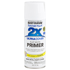
You need a primer if you are going to brush on most paints, especially the acrylic 2 fl oz craft store paints. There are a lot of products out there. Here's one I've been using (just finished my first can of it):


Rustoleum Painter's Touch Ultra Cover 2x Flat White Primer

This gives the 3d printed parts a matte, 'unglazed ceramics' type look.

If you just want one flat color, and you want to save time, there are lots of "paint+primer" products available that will do just fine.

Painting
With brushed on acrylics, multiple thin coats are the way to go. The first coat won't be completely opaque. Most of these regular styles of paint will have a rough enough dried surface to allow painting on top of them. However, some formulations, especially specialty glossy/metallic/other types, will end up creating a very smooth dried finish and you won't be able to get other paints to stick on top. Test first if the part you are painting is important.

Undo-ing your work
If you hate the paint job, it may be possible to chip off the paint and primer without damaging the plastic surface. Some paints will peel away off the primer, others will chip off with the primer and a little force. You can use a needle to get into the small areas, but in creases the paint will be impossible to get out. Soaking in water can help loosen the paint. After the part is fully dried you can start again.

Finishing
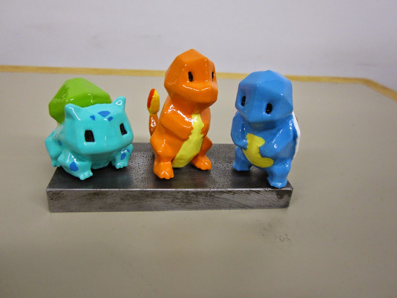
You should apply a protective coat after the piece is fully dried. The primer and paint tends to chip off quite easily otherwise. One of my favorite finishes is this one:


Krylon Triple-Thick Crystal Clear Glaze

This finish results in a glass/glazed ceramics like look. It's also fairly durable. Be careful when spraying, because it is VERY STICKY. If your part accidentally falls over or brushes against something, you're basically out of luck... I had a part fall over onto the Styrofoam plate it was sitting on, and the Styrofoam dissolved and little bits of it were stuck firmly all over the part. I ended up quickly soaking and then scraping all the paint and starting from scratch.

Another suggestion
I just found some PlastiKote Metal Flake (in blue) in storage at the hackerspace and tried it out. It is beautiful. I don't have any photos of my stuff just yet, but here is an example from someone else:

PlastiKote Metal Flake Blue Example

It works fine on the primed ABS plastic (haven't tried it on bare plastic) and makes the piece immediately look like glossy glazed ceramics.

As I try more stuff, I'll post more in this series. After the holidays you will be able to see photos of all the finished pieces.


Monday, December 15, 2014

First set of MOARbots


The first set of MOARbots are coming together. Pictured above are the 4 cart bodies in this set. I will be assembling them before I leave for the holidays, so that Sector 67 can bring them to Saturday Science. They won't be doing anything fancy; the game is human-controlled bumper cars. The setup:

  • 4 USB game controllers
  • 1 transmitter wixel
  • 1 receiver wixel per robot
  • 6 or so red LED 'damage' indicators per robot
  • Some limit switches and wire bumpers
  • A modular set of acrylic arena walls, hinged with duct tape, and with holes for snapping the supports into it (to keep the robots from ramming down the wall)
The game works as follows: Control (joystick) data gets sent out from each controller to each robot (if the controllers don't switch USB slots, it ought to be possible to color code the controllers to the corresponding robots). Each robot starts with full health, so no damage indicators are on. Each time the rear bumper gets hit (note the rear is the side with the marble) all the LEDs flash and the robot is in "invulnerable" mode. After "invulnerable" mode the LEDs light up to reflect how much total damage the robot has suffered since the round started. If all the LEDs light up, the robot enters a slow blink mode and stops moving, regardless of controller input. The supervisor (the person sitting at the computer that ties this all together) can hit a key at the Python script to reset the game. This sends a reset signal to all robots, who reset their damage indicators and start anew.

This game was designed specifically to allow one way communication only (controller computer to robots only), and to not involve the webcam.

Upcoming posts are expected to be MOARbots and holiday season related. Happy Hannukah and so on.


Tuesday, December 9, 2014

Chocolate Mold Round 1

I finally did my first silicone pour. The first run I messed up by reading off the wrong set of instructions and mixing with the wrong ratio as a result. The second one worked, with only minor issues. These results are far from beautiful because in my rush to put out a few 'prototypes' I decided to try microwaving chocolate instead of double boiling. The microwaved chocolate was unevenly heated and ended up being hard to work with. Next time will look much better!


Things I have learned:
  • The cured product seems very good--surprisingly durable and flexible.
  • The process of pouring takes some finesse, but I'll post about that after the next few pours.
  • The texture of the wood ultimately did transfer onto the silicone, but those fine details got lost on the chocolate step.
  • The process of melting and pouring chocolate is not easy either. Each product behaves slightly differently as well. Though 'supported' on the package, microwaving is not a good method.
  • A lot of the crappy candy melt stuff I bought tastes like crap. Big surprise. Pretty but disgusting in flavor. Good for practice I suppose.
  • I designed this bar to be 3/8" thick in the body and 1/8" thick on the details (the raised scales). That's a pretty thick chocolate bar. I tried pouring one with a much thinner body but it cracked in the removal process.
  • Ideally, I will find a way to melt the chocolate until it reaches as low a viscosity as possible. That will make the process faster and easier, and also make the chocolates a lot nicer looking.
I ordered a block of HDPE to mill my next positives. That will get rid of the wood grain issue. There should be enough material there to mill about 6 different positive blocks, so in addition to remaking this one, I will try a few more designs.

I will also give these a try with colored ice, to make 'stained glass' type window panes to put outside this winter. One advantage of Wisconsin is it is a great environment for ice and snow art. The weather will stay well below freezing for months at a time.

Happy holiday making!

Sunday, November 9, 2014

Mini Cart / Build Madison

Build Madison is almost over, so I get to sleep soon. I found a helper for the mini cart project, a design which will also be part of the MOARbots framework. The mini cart has immediate appeal--it can use cheaper motors and batteries, and more can fit in the arena for large multi-robot events.

Here is the mini cart alongside the regular cart.


The mini cart motors were pulled from a misc. motors bin, so they aren't exactly the same. Also, one
of them had been previously used and wasn't in good condition, so this prototype really only can turn one wheel on. The point however was to prove that it is possible to use el-cheapo small toy motors, with 3d printed gears, to move a cart.


I spent most of my time though working on an omni wheel design. I found some tackier heat shrink in large diameters that works very well for tires. Other than the tires and axles (small finishing nails), everything else is 3d printed. The triangular shape allows for two halves to fit together snugly to form the final wheel assembly. This design has very little room for error, which especially problematic given the variance on prints. A redesign should be coming soon.

One more thing: the MOARbots project has a wiki now. It is minimally populated but it will be growing A LOT especially as I get ready for a set of UW students who will be working on this project for independent study credits. I'll link it often in the future as well. https://sites.google.com/site/moarbots/home

Thursday, November 6, 2014

MOARbots, the ESP8266, and more omniwheels

This project finally has a title.

MOARbots: Modular, Open-Source, Affordable Robots.

Progress on MOARbots is as follows:

I learned about the ESP8266 through Hackaday and decided to purchase a few. It is a $5 WiFi chip and programmable microcontroller to boot. I haven't been through the recently translated datasheet yet, but it seems to clock at 80MHz and have 16 GPIO pins, 2 of which are broken out on the boards I purchased. It will require tons of development to be usable for MOARbots but the community is very interested in it to make Internet of Things happen at a low cost point, so I won't be alone.

I decided to make a micromini version of my omniwheel bot, based around three Pololu motors I got for free. The motors are far too expensive at $15 to be part of the framework's suggested bill of materials, but for now this is a good project to test out my designs for small 3d printed omniwheels. I'm working through some designs, and here's a render of iteration #1.


Hand forming steel wire made sense for circles, but not squares. I didn't want to take the better part of a month to build a CNC wireformer type machine, or to bother making simpler hand jigs for preset sizes or shapes, so I've rethought the design and will aim to use small finishing nails, which are cheap and widely available and don't need to be formed.

After the monthly Sector 67 meeting, a few people test drove the 2-wheeled cart. Despite the very simplistic control scheme (pre-programmed forward, left, right, stop routines), users were able to drive the cart pretty smoothly, even getting interesting drifting action at top speeds. The battery was barely drained even after a solid 20 minutes of driving, and with the addition of a heat sink the L298 motor driver was doing just fine (the heat sink is very necessary though). So this iteration of the cart is a success I think, and I will just need to buy some more L298s before I have everything I need to assemble 6 more.

Saturday, November 1, 2014

Omniwheel Robot 1

Before giving a talk at the university, I decided it would be a good idea to...spend 20 hours straight working at Sector on a omniwheel robot prototype. I only got a half hour sleep before the talk but I guess I must have been coherent based on the response from others.

See my slides on Google Drive at this link.

Here are some photos of the omni wheel bot.


Omniwheel before assembly of beads. The wooden block is a jig for mounting the press fit gears on the motors. The vertical mount design isn't great, as weight of the robot causes the mount to flex downwards a little, which pushes the gears together more tightly, which increases friction. That will be changed in the next version.


Some of the beads before mounting. I loaded them up on a piece of wire and coated them with Plastidip (black) or Flexidip (red, pictures on the full assembly below). It is better than nothing but still not a great solution. So far my best solution has been to skip tires entirely, and run the robots on rubber mats. I'm still looking for a good tire solution though.


The fully assembled omniwheel bot. I tested it with the power supply, and it does move. It draws a bit more current than planned (5 amps or so) but I think with a little redesign I can make a lower current draw version.

I got a bin full of more stuff donated to Sector, including some really nice motors to play with. The primary goal is still ultra-low-cost stuff, so I will start looking into sourcing cheap motors. My framework will come with practical notes, including 'buying guide' type notes for some parts, as well as design files, code, and everything else.


Tuesday, October 28, 2014

Omniwheel Prototype 2

I made a second prototype for the omniwheel. The point was to test out a few things:
The knurled shaft on these smaller set of motors is pretty long, so I made the gear the full length of that. That helps keep the fit straight. I will be increasing the channel length of the other press fit gears I print from now on, so that getting them straight isn't a matter of skill with the mallet or arbor press.

The 'tires' are made from inside-outed waterproof heat shrink. The inside is tackier, but you can only inside-out small pieces at a time. The adherence isn't great unless you get the plastic just melty enough to conform to the tire without collapsing/deforming. You have to hand carve away the excess. Not a good method. I've ordered some 'silicone heat shrink' on eBay that will arrive in November; hopefully that product is different than this one. This could work great for beads with larger surface area if it came with the tacky side out.

Previously I had tried Rustoleum Flexible Rubber, but the droplets were far too big and the whole thing ended up being a globby mess. FlexiDip sprayed on nicer with a fine droplet mist but it wasn't all that rubbery. Plastidip seemed similar but a little thinner (more solvent per less payload) but this needs more testing.

Here's a picture of my second desk. HobbyKing batteries arrived today and actually seem like a good fit and weight for my cart robot design. I've already redesigned the cart gearing system, so all that remains to be done for the cart live demo is to figure out a the small gear press fit going on sideways problem, and to resize and refine the motor mounts.


Sunday, October 26, 2014

Omni Wheel Prototype

There was a plan this week to give a very small talk about my robot to a very small group of people. Then it grew into a much bigger event--university departmental computer science talk. Suffice to say, now I'm pretty amped up as well as reasonably nervous.

All this required me to think very hard about what I've been doing, what sets it apart, why it is useful, and to whom. And one thing that came out of that was me realizing that some omnidirectional wheels need to be part of my framework because some users in my talk audience will need them. Existing omnidirectional wheel designs on the web didn't fit my design principles and needs very well. So I designed the one below.

With beads assembled

Frame only

The key things about this design are as follows:
  • It only requires one piece of hardware--some wire. I have some 16 or so gauge steel wire, but you can pick anything that feels right to you for your size of wheel, and input those dimensions into the OpenSCAD file.
  • Everything can be changed easily in the OpenSCAD file. Number of beads, shape and size of the bead, gauge of the wire, etc. This will be more true after some cleanup on my part, when I get it ready for release on Thingiverse and elsewhere.
  • Everything besides the steel wire is 3d printed. It is often easier to 3d print beads than to find beads that fit the wire closely.
  • The 3d print does not have to be split in two in order to print. Assembly is simple and doesn't require any 'finicky steps.'
    • This is because the channel for the wire is opened up, specifically at the point where printing more of the channel would break the 45 degree rule of thumb for 3d printing. It has a snap-in kind of feel.
    • Hot glue can be used optionally to help tack down the wire where needed.
    • The wheel hub/gear module will be added on top in the final version without any fuss. To illustrate how this can be a problem with other designs, consider the version where an enclosed channel is created by printing the wheel in halves split along the central X-Y plane of the wheel. In order to not break the 45 degree rule, you have to print the inside faces up. In order to print the wheel hub though, you need at least one outside face up. (My solution in that case would have been a triangular channel).
I'd like to come up with a few more variations on this, and maybe tackle a similarly informed design for Mecanum wheels or two-layered omni wheels.


Here's a first 3d print. The beads will be spray coated with Flexible Rubber, a product sold mostly for sealing up cars and boats. They'll be loaded on a skewer and finished in bulk, which is an important point when you have this many parts to finish. This will also make it more feasible for me to spend the time to apply multiple layers, to get a good thick rubber tire on each.


Looking good--only minor design changes and a little finishing work is needed for this particular mix of the OpenSCAD parameters to be more than a demonstration prototype.

Oh, and I should mention: this wheel cost about 63 cents! That's 60 cents of 3d printed plastic and a few cents worth of steel wire. The wheel is 6cm in diameter.

Thursday, October 23, 2014

Robot Cart Progress -- It Drives!


First assembled prototype. Preliminary tests show that (a) it is capable of driving smoothly and (b) it doesn't draw too much current for the L298 motor driver. Spent yesterday evening hunting down flyback diodes at Sector and I even found two additional L298s, as well as a handful of extra large breadboard-compatible tactile switches (pictured left, in the background).

The Wixel code for the transmitter is done. Next up is integrating the PWM code to the receiver modules, and creating easy to use skeleton code for competition participants to come in and edit.

I still need to get additional batteries, a suitable USB camera with a good wide angle of view and OpenCV compatible drivers, and a few other parts. So far so good though.

Edit: Minor Setbacks
I bought these batteries from Adafruit and these batteries from Sparkfun. The Sparkfun batteries provide enough current to get the cart moving, but if it hits any obstacle and stalls, this triggers the overcurrent protection. Toggling the power on and off resets this protection. The Adafruit batteries can't even run the motors unloaded (wheels not in contact with the ground). They twitch, then die out (presumably, overcurrent protection). This is a shame, because I purchased them on the assumption that they would provide a maximum continuous 2C discharge rate, which they aren't, as far as I can tell. The datasheet seems to say that (bad formatting on it makes it hard to read).

In any case, Sparkfun's comment system and tendency to better document products on the page makes me feel a lot better about purchasing from them when they have the stock I want. Unfortunately neither battery will quite do for my needs, so I need to go back and rethink this.

Also, I wasn't able for whatever reason to get the wixel-pwm library by dpark83 working for me. It isn't particularly well commented which makes it difficult to use. I did find this simpler code, which works well enough for me to use instead.

Since the price for these robots is already quite high, I'm going to try and re-use some parts around Sector. Namely, a bin of old cheap lithium ion batteries without any protection circuits, and a bunch of scrapped prototypes for a battery board that has no documentation, but a ton of features (presumably). Or, in the interest of time, skip the reverse-engineering on the battery boards, and just triple check to make my circuits don't look too explode-y, and go protection-less. So far I haven't made any really serious mistakes with my wiring prototypes...

Sunday, October 5, 2014

Robot platform in progress

Entire post got deleted while I tried to fix the alignment between the photos shown below. The Blogger WYSIWYG (what you see is what you get) editor is terrible for images, column layouts, etc. In short: I've been working on a lot of things recently, but haven't posted because posting takes time and effort and you need to get good photos of stuff and find a good stopping off point on those projects that never end.

The biggest thing I'm working on now is a robot platform that will be open source. The brain will be the Wixel and the cost will probably be in the $50-$60 to build it yourself. The gear/wheel/mounts prototype are shown below. To give you a sense of scale, the wheels are 9cm diameter and in the assembly shown below, the distance from the wheel to the motor terminals is about 7cm. The first goal for these will be to build seven of them myself and use them to run some fun programming competition aimed at adults/experienced programmers at Sector 67. Past that, I'll probably use these with an Arduino (in addition to, not instead of the Wixel) if I teach a robotics class this summer again.


Wednesday, August 27, 2014

First CNC Project

Walnut box, milled on the CNC (apologizes about the photo quality...point and shoot, nighttime, poorly lit apartment). This is a prototype. The glass circle with paper will probably sit on top of the box, not inside. I'll make another inlay for the circular groove in the top and bottom inside surface of the box. The design will have plenty of variations, and will be the basis for all my holiday gifts this year. I will also probably sell similar boxes on Etsy. There will be lots of variations in the details and embellishments.


The nicest thing about these smaller boxes is that they can be milled out of smaller 'scrap wood.' I have a near limitless supply of this stuff at the hackerspace, all for free. The pieces are usually the leftovers of a larger project, so they are already prepped (in other words, they were run through the planar/joiner). In the spirit of 'waste not, want not' I will probably make extensive use of this materials resource.

Tuesday, August 26, 2014

More FreeCAD

I've been doing more FreeCAD. It works pretty well for me, since I'm making simpler parts. To compare some tools I've used in the past:

  • As a beginner, Autodesk was pretty overwhelming, and I felt like I needed hours of tutorials/poking around the interface in order to find the commands/buttons for the simplest features to make simple parts. Large, resource consuming software, only free for me as long as I am a student.
  • Sketchup was really easy to pick up but annoying to use for engineering/fabrication stuff because it is not parametric/constraint-based modeling software. I was using it for 3D printed parts and a lot of files would not slice properly for reasons that were very difficult to diagnose or fix. Quickly ran into features I needed that were not in the free version.
  • FreeCAD is missing a lot of features I'd like, but so far it has always been possible for me to find a different feature to use in order to achieve the part I want. Free and open-source.

I want to mill some very small boxes out of some scrap pieces of wood, so I designed the box below, which can be easily customized. For a simple piece like this though, it makes more sense to just prepare a set of 2D lines in Inkscape or similar software, which is what I ended up doing afterwards. At the CNC machine, I then use another piece of software to set up all the details of how the machine will cut each vector path depicted in my 2D file.


Hopefully these boxes work out. If so, I'll make a bunch with different designs and embellishments (engraving, marquetry, decoupage, rock inlay, etc). They will make good gifts. I also think they may sell well on Etsy. It would be very practical to use my hackerspace membership to cover my hackerspace membership fees.

Monday, August 25, 2014

FreeCAD tutorial

I discovered the Windows "Snipping Tool" recently. So here's a mini-tutorial to preface the FreeCAD intro tutorial.

  • If you have Dropbox enabled to automatically upload screenshots, disable that, as it appears to interfere (did for me on Windows 7)
  • Open Snipping Tool and press ESC, so that the text says "Select a snip type from the menu [...]"
  • Set up the shot you want, then hit Control + Print Screen
  • Select the snip type you want and get the shot. The window you had open before will be frozen so you can move the mouse around now without losing hover text and drop down menus.
Since I discovered this, I've been taking the time to document things I learn to do in various software. The main reason is that often I come back later and can't remember some particular trick or button or whatever, and having a screenshot describing it is really nice.

So, here's a FreeCad tutorial along these lines. This version uses FreeCAD 0.14 (except for the first few screenshots, before I realized I should update my old version). You'll want to click on the images to view them at a more reasonable size. We'll be making a very simple square part with some holes. This tutorial goes through everything in detail and step by step, for those of you who find that kind of thing useful.

Step 0: Get FreeCAD
Get FreeCAD here.

Step 1: Start it up
Start up FreeCAD. Click on the top left button (circled below) to create a new project.


Friday, August 22, 2014

Borrowed Hair

After spending a lot of time on hair experiments, I finally broke down and just grabbed the Mass Effect meshes. I couldn't find anything better for polygonal hair to get started with. I figure I can use these as 'base' models and edit and elaborate on them.

I also heard that the newest versions of Makehuman are supposed to have some new hair models but I can't find them...I got the latest nightly build and it only included the same old, same old... 

I played around with some rudimentary UV unwrapping as well, adding a single eyebrow to the render below. I need to get my Wacom tablet out and start painting again.


For the hair mesh above and meshes in this style, there are a few ways I might use them:
  • Blocky style, as above
  • Carefully wrapped textures with transparent edges, for a wispy look emulating particles
  • Actual particle hair along the mesh lines, possibly with Hairnet
  • As a starting point for sculpting different hair
I'm almost ready to start making a bigger project instead of just endless test renders. I've been introduced to modeling, sculpting, physics simulations, particle systems, UV unwrapping, materials, rigging, shapekeys, keyframing, and more. I've figured out a good resources for inanimate objects, for heads, for bodies, for hair, and for clothes. I can endlessly raise my standards, OR I can get Project 0 in gear and actually start telling a story.

Sunday, August 17, 2014

General frustration

Hair is still proving difficult...playing around with different things but I haven't figured out what kind of hair creation pipeline is going to work best for me yet.

I'm glad sewing weights finally got added to Blender trunk, but of course getting the cloth collision simulation just right is still tricky.

Freestyle still feels a little under-developed for my tastes. It works great for boundaries between objects and stuff, but the crease-based outlining (checking to see if the crease is sharper than some user specified angle) doesn't work so well for organic objects like human faces.

I spent some time thinking about what kind of thing would work well. Say you shoot a ray out from the camera and it intersects with two outer faces of the mesh (you could just deal with faces with normals pointing outwards, to ignore the inside faces of walled meshes), then measure the distance between those two intersection points. If the distance is great enough (compare to user specified value) then that would indicate that the region of mesh in front is sufficiently 'in front' to need to be somehow outlined compared to the region in back...but I haven't thought through that any further, so I'm not sure how you'd figure out where those lines belong exactly. Maybe I can hack something together using Z distance data to camera and the node editor, not sure exactly.

Anyway, to recap, what I'm looking for now:
  • Find a reasonable way to make hair that looks good and doesn't take forever
  • Better understanding of how to choose good physics simulation parameters in general, for cloth, hair, etc.
  • More NPR line drawing styles...

Just for fun, I played around with this face mesh I've been using, and Freestyle. The use of a high crease detect angle for Freestyle (170-175) gives a nice sketchy effect. I'd like it more if it wasn't the only effect I can get for faces. If I turn down the crease angle I'm left with just the eyes and the central line of the mouth, basically.


Shapekeys are still proving to be quite easy; the above took 5 minutes for each (half-shut eyes, slightly parted smile). These results are helping me keep my sanity while I try to get the rest working.

Edge split modifier on the Freestyle generating mesh can help get a bit:


Friday, August 15, 2014

Particle Hair Physics Progress

Alright, some progress on the frustrating particle hair physics.

I checked out this model which uses particle hair which is attached to an invisible scalp. I eventually figured out the invisibility bit (object tab, "Wire" and "Transparency") which was more convenient than my previous method (moving the mesh that created the force field to another render layer). The scalp is copied off the original head then slightly scaled up.


Having the scalp a bit larger than the actual head helps fix the issue of hair getting stuck on/inside the mesh due to it starting out too close to it.

A quick test to prove the physics is working:


Next steps for hair:

  • Give the character a haircut, also using different particle system groups for different areas of the hair on the scalp
  • Figure out a way to keep the top of the scalp from looking so bald (see the first image; that seems to happen a lot)
  • Get rid of hair that is still clipping the head, perhaps by adjusting force field settings
  • Play with settings to get different looks (something a bit messier and a little less 'every hair in place')

Tuesday, August 12, 2014

Hair Physics and Face Remesh

I'm trying to do hair with particle physics. However, issues include:
  • By default the hair falls through the scalp. The workaround I used is to create a duplicate mesh to emit the hair, then take the original head mesh and make it have a force field. But children hairs still collide and also I haven't figure out how to make the duplicate scalp invisible. (Edit: it seems that this is something being worked on now, but that the force field will have to do in the meantime).
  • Exploring parameters, computationally intensive task is created, Blender is not responsive...force quit and try again.
  • Getting a very bad case of the hiccups. Not a Blender issue but it compounded on my frustration. The hiccups were strong enough that they made me mis-click repeatedly.
  • I happened to play around with Freestyle and this woodpecker blend and discovered that I can make a nice outline around particle systems. See the tufted areas on the bird body below. I'm having some trouble replicating that with hair so I need to figure out what makes it tick.


Also, I attempted many automated methods of retopologizing models to go from tris to quads and nothing worked perfectly. The "tris to quads" tool did an alright job. I highlighted some of the leftover triangles for emphasis. There are quite a few.


Remesh failed. I played around with the options but nothing usable came out.


Other settings for remesh. Could be used as a creepy type effect. Shrinkwrap did a similarly bad job.

Monday, August 11, 2014

Learning to use shapekeys

Following the tutorial "Creating an Advanced Face Rig - Part One" I learned how to use shapekeys and played around with this model by Norby again.


It's a start anyway. Smiles are easier than frowns. Eyelids are tricky. Brows are easy.

If you are following the video, there's a tricky bit (reflected in the comments) where he forgets to mention the use of "New Shape Key from Mix." He implies that pressing the "+" key in the Shape Keys menu will create a new Shake Key from whatever mix of shapekeys is set. Actually, you have to use a special button in the drop down menu to do that, as such: