I'm preparing a robotics exhibit for a local museum that is opening up soon. To that end, I learned how to weld just now (I'm not very good yet. Also now I'll smell like welding all day).
The exhibit is simple--drive a small remote controlled car around a map of the city, from a monitor that tracks the car and displays a birds-eye view camera image, auto-rotated to the car.
The biggest hurdles:
Light weight and high capacity battery (but low max discharge rate--which is fine, I don't need a high discharge rate)
Sleep mode for the wireless radio and microcontroller to conserve battery when nobody is using the exhibit (chose the Wixel here, for reasons I'll cover in another post)
Safety against, stall, over-current, under-voltage, and other battery damaging conditions
Making sure the parts the user touches (console, perimeter wall) stand up to the forces users will likely put on these
First impressions: Quick-start was very easy. Installed drivers and software on Windows to get this screenshot, but you don't need to, as the scope has a tiny display.
In the image above I am bringing a flashlight closer and farther from the sensor. The green shows the phototransistor circuit output directly. The red is the output of the comparator circuit (LM358N, CNY70 if you want the parts. Just what I keep in stock, not chosen for any other reason. Don't turn on the CNY70 LED for this application, durr).
I was able to get it to robustly sense when I walked under the fluorescent light fixtures in this building, holding it at chest height.
More on this later.
EDIT: One more fun image.
My fluorescent bulb desk lamp apparently pulses on/off with a cycle taking 7ms or so. The other pattern (where the waveform is getting "pinched" and then expanded) is aliasing from the slow sampling frequency of the oscilloscope (or at least the points drawn in the software) at this large time scale and the 7ms lamp pulse.
Four years ago I made my first printed circuit board using EagleCAD and purchased a few units using BatchPCB. It was a version of this current limiting circuit with R5 as a potentiometer, which lets me modify the cutoff current. By the time the boards arrived I probably had exams or something, and so the project was forgotten.
Today I was trying to clean my desk, but I found the boards and got distracted. I scavenged around Sector67 for parts (making backwards progress on the desk-cleaning situation) and populated the board.
When the output draws under some current limit (can be modified by the potentiometer), the green LED is on. When the output would draw more than that limit, the red light turns on, and the output current is limited to what flows through the red LED and resistor in series with it. The concept and operation is described in detail at the Instructables page of the source for this project: http://www.instructables.com/id/PC-Power-12-V-Current-Limiter/
I made the traces thinner than I would have liked. It was my first time getting a PCB made and I didn't realize that I had forgotten to set the trace width until it was too late. The default trace width is probably fine here anyway. It feels good to finally wrap up this project. I could go further with it (compute some values, measure some values, stress test the board, refine the design) but there are hundreds of other projects that will probably take priority.
A MOARbots volunteer (Scott) made some python visualizations for the data stored from the multiple waypoint navigation competition.
Each path comes from a different (completely or slightly) piece of code running on the robot. The waypoints are the large gray circles, and are always in these same pattern, though sometimes the board was rotated (the tags were physically taped to it).
You can see the curve of the path segments in robots that did not account for the differences in output wheel speed relative to PWM (pulse-width modulation) value between the left and right motors. The actual physical robots were not the same between all these runs (the number at the top is just the robot ID tag which is removable). They all curve left because the right hand wheel motor is in the bias direction when moving forward, but the left hand wheel motor is in the anti-bias direction.
The target is considered reached if the robot's tag center point is within 20 units (pixels, but our camera never moves) of the goal point tag center. The score is computed as such:
Score = 120 - t + 25*n t: time elapsed in seconds since trial started n: number of waypoints visited Total number of waypoints: 5 Trial ends if the score reaches zero
The maximum score is therefore 245, for a theoretical 'teleporting' robot.
The competition can be summed up by the two key challenges: (1) Figuring out how to drive quickly towards a single waypoint without overshooting the goal, and (2) Computing the shortest path given the locations of the goals and the robot start position.
The robot in the above visualization did a little too much zig zagging. It also didn't compute the best path.
The robot in the above visualization correctly figured out the minimum length path given the tag locations and robot start position.
While the UW students were off on spring break, I took some time to work on old projects from "The Big Project List."
I found a scrap of plywood which was just the right size to mill out Curio Shelf Revision 1.
The pieces before assembly:
Due to a mistake in the lengths of the dividers, the shelf curves outward in the middle. Not a bad look, but not a look I'd keep in Revision 2.
Another project is a bamboo magnetic board with a french cleat in a V shape for the wall mount. First I did a quick mockup in OpenSCAD to visualize it. The small piece here would be mounted on the board. The large piece would be mounted on the wall. In the first image, the wall would be on the positive x-axis side, and the board on the -x axis side.
Here's the finished cleat. It doesn't look very neat however it is not visible when the board is mounted. Now it is easy to remove or replace the board on the wall. This means you can use it as a screw organizer that you store on the wall.
MOARbots is now on github: https://github.com/MOARbots/
Here's a video of one of the waypoint navigation routines that have come out of the UW independent study.
What's next? Yet another revision to the parts list. The new MOARbots will be based around the Teensy and the ESP8266. Using the ESP8266 by itself (with something like this board) is still on the table but will have to wait a bit. Using the Teensy has the advantage of being able to make them into Teensyduinos. The Arduino programming language/environment is easy to use compared to writing in C. And, if I'm willing to wait a bit, the hobbyist community will develop the tools I need for the ESP8266. Take a look at this project, for example: https://github.com/nodemcu/nodemcu-firmware/
One of the most important things that has happened to MOARbots recently is the expansion of the team of volunteers working on it. Thanks to the Sector 67 community and the University of Wisconsin community, MOARbots is now more than just my own personal project.
Lastly, here's a teaser of one more cool direction MOARbots might take:
Last post I realized that I needed to redesign the gearbox for my most recent set of robots. I added a compound gear. This brought the overall ratio of the gear system to 30:1. I also switched batteries, to reduce weight, going from a 113 gram battery down to a 46 gram one. I got rid of a few other parts too (acrylic panel and standoffs that created a battery bay which was not needed for the smaller battery).
The motors don't overheat now. Since the motor output shaft moves faster, there was more electrical noise on the system, and I had to add the ferrite chokes (otherwise, the Wixel locks up).
Here's a video demonstrating the new design in a simple mechanical/electrical test.
Below is another video, showing a simple pre-determined routine (no sensors). This was coded by some of the people participating in the independent study.
So I've recently focused on using the "130 size" motors that are widely available to power my robots.
I ran into one major issue today though. With the robot fully loaded (I put a pretty hefty battery on it, about 115 grams) the load was excessive, and within 1-2 minutes of use the motor overheated. As it overheated, the robot began to slow down. Eventually, the motor shorted. When it did the motor driver was zapped. In this particular instance, the motor driver then shorted the motor voltage line to the Wixel, which zapped the Wixel too. The magic smoke was released, and the electronics were no more. How disappointing.
My robots were operating at the "Heavy Load" region; bad news
Mostly though I was bummed out to find that I need to do a lot of redesign, ASAP. Pride can get in the way here, and I'm conscious of that. Just because I sank a lot of time into a design, doesn't mean I should be hell-bent on polishing it until it more or less functions. Perhaps it is time to take things in another direction, as frustrating as that is to admit.
So, I did a little more late night reading. I started by returning to this video, which shows a robot that appears to be made with CD drive motors, belt drive, bottlecap wheels, and a bead caster. It is zippy, seems to feature some kind of lightweight battery, and it seems 'low cost.'
However, I can't seem to find cheap brushed CD motors in bulk. The salvage on eBay is surprisingly expensive, and also not always sold in uniform lots. The process of salvaging is time consuming and parts may not be available to all.
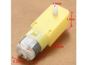
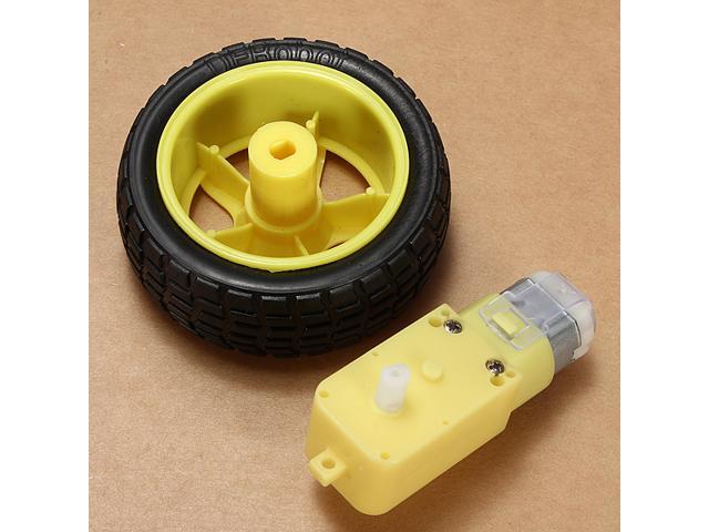
Below is a motor/wheel/gearbox that is probably a really good option. It seems to use the 130 size motor or something similar, though I haven't gotten a sample set of these yet. At $3.xx if you buy them in groups of at least 2 (that includes ePacket shipping; these mostly ship from China), that isn't a bad deal. Ultimately given the time and plastic costs with 3d printing wheels and gearboxes, I think I should have been trying these out.
I think perhaps I had a bit of confusion as the MOARbots mission evolved. In the beginning, I was really keen on using some of my collection of motors, many of them salvage. Over time I realized that I specifically wanted to avoid salvage for reproducibility reasons. Part of that was reading over so many unhelpful and poorly written Instructables...
Pictured above is SWARMbot from AFRON 2012. It uses some very small motors hooked up to bottle caps with direct drive, and runs on a single LiPo cell. Direct drive is something I found really tricky with bots on a larger scale, and I wonder how much weight you can put on this thing before it stalls. Depending on your needs, that may or may not be a problem.
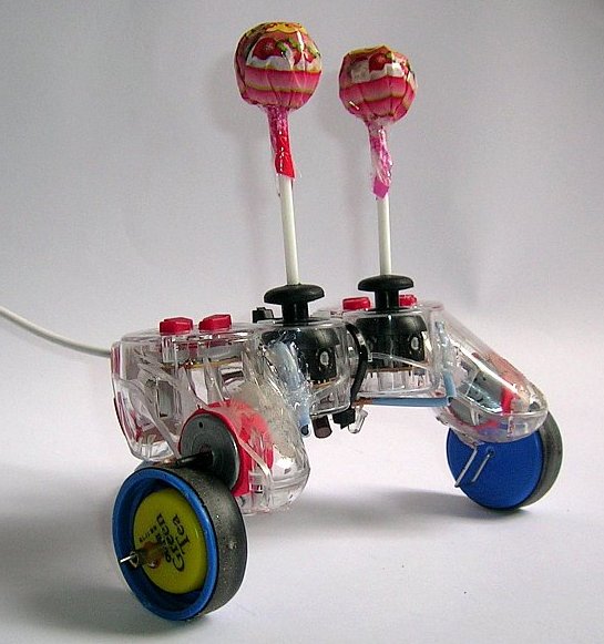
This was the other intriguing design from AFRON 2012, the LollyBot. I mostly liked the style of drive with the rubber tire friction. I was pretty surprised to see the price on the cheap dual stick controller listed as about $3.80...the link didn't work for me, so I don't quite believe that price yet...
At this point I was feeling a little bad, so I decided to remind myself of what MOARbots is still important for. Here's a list:
1. A collection of modules, resources, and general knowledge instead of a single model of robot.
Up to now I've still had trouble finding information about what to buy, where to buy, design considerations, how to pick and choose, etc. Even with some of the excellent designs above, they provide just instructions on how to build their design. One of the goals of MOARbots is to generate a big, easy to navigate set of resources that help you understand how to successfully pick and choose design elements. I'm learning a lot in this process that I want to share, but I don't think a big rambling article is the way to share it. I need to think of a good format.
2. Digital wireless while maintaining low cost / Code
The Arduino is very popular, but adding it with some wireless module costs more money. Because the Wixel was actually a little cheaper and included a wireless radio, I decided to go with that. The Wixel community is a whole lot smaller than the Arduino community and it shows. Hopefully part of what this project will do is contribute to that community the sorts of resources that people doing robotics projects similar to MOARbots will need. What is needed? Mostly glue between existing code modules that others have written, instructions to make use easier.
Of course, if I can find the time, I'd like to also start trying to switch the Wixel out for the ESP8266 instead. as I've mentioned before. Pointing people toward/providing a tutorial for getting started with AprilTags could also be a goal. By using something and inviting others to follow you add to a community, and then the community turns around and contributes back things you find useful, most importantly perhaps being posts on the internet about solutions to problems.
3. Cheap omniwheels
I left my omniwheel project alone a while back to focus on the other aspects of MOARbots, but as far as I can tell cheap 3d printed omniwheel designs still aren't really available online. Of course by the time I have a chance to finish mine, I'll find out somebody else finished it for me. But you saw it here first folks! 3D printed plastic plus finishing nails and rubbery heat shrink. That is probably my most original mechanical design contribution. My omniwheel design.
4. Alternatives/Redundancy/Options
I think it is better to have more options than just one. Users will surprise you, and you can't really predict the things an arbitrary person searching the internet for low cost DIY robots will need out of a framework/platform. Having a lot of alternatives is a good thing.
Wrap-up: what's next? Well, the most pressing issue for me is to fix my fleet of 10 robots with overheating motor issues. I'd like to use the same parts because they have already been purchased, so I'm not switching now to a design that is too drastically different.
One final thought: I want to reiterate how important it is to have a central knowledge base that is easily navigable. I keep finding gems hidden in obscure forums online. From the link describing this video, this description : "Its a belt drive car. Used a bobbin from a sewing machine on the axle and used a bicycle tube cutout as the belt. This is working for now, but I need to find something a bit better as the connection between the motor and the axle is too loose."
I wish the internet had a good user uploaded content driven website focused on listing 'household' items tagged with different uses for them. Then you could see more by following links to builds and writeups. You could also watch prices and find sources for buying in different quantities.
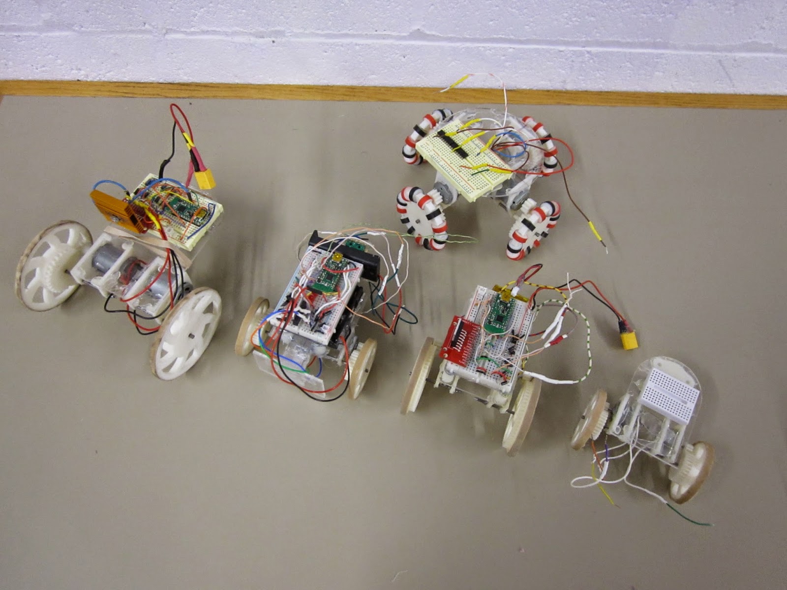
The 5 'models' of MOARbot that I've made so far. MOARbots doesn't really come in 'models' so I put that word in quotes. Overall the above robots represent my exploration of a bunch of different design elements. MOARbots as a project is just the framework/resources/suggestions one might need to pick and choose their own elements and make their own set.
When I have a need to create a set of robots though (for AI control, remote control games, whatever else), I do tend to want them to all be identical. So then I'll refine one design, and print out n many more. In that sense it has become convenient to refer to the designs as 'models.'
"Big Cart"
Above is the very first MOARbot. I sourced parts to make a full set of seven identical robots like this one. The motors are the very beefy RS-385SH by Mabuchi. These are geared with just a 3:1 ratio (I tried a 2:1 but with the battery weight, the thing stalled too easily). As a result it is very zippy. Notice the black marks on the rubber band tire--some Sector 67 members had fun driving this thing around quite a bit. Heat sink is definitely necessary. The stall current of each motor is 4 amps, which means that at full stall they will burn out the motor driver, which is spec'd at 4 amps total for both motor channels. The proper solution would be to use the current sensing pins to stop the motors when they draw too much current. The quick-fix solution I implemented at the time was to remind all the drivers that they should hit the brake key every time the robot ran into something.
"Omni Prototype 1"
This is the first omniwheel MOARbot prototype. It used 4 unknown motors pulled out of a bin. The omniwheel black and red 'beads' were spray coated with some products to make them more tacky, but that ultimately did not provide enough traction. A quick test showed moving a pair of motors took about 4 amps continuous current draw. The wheels slipped a lot on most surfaces as well. I came up with a much better design right after, but haven't yet finished work on that project (very very close though).
"Small Cart"
This is the smallest design so far. The motors were pulled from a bin, and only one worked. The robot was successfully able to drive in circles with 2 AA batteries (alkaline). This convinced me to try some smaller motors for similarly sized robots. If I were to go smaller than this, I'd switch away from 3D printed gears altogether and use rubber belts (like this robot that uses them with little CD drive motors). A robot like that could be built without any 3d printed parts, which would be appealing those who don't have access to 3d printing. A MOARbots project to source the parts for and build a set of those will happen most likely this year.
"Bumper Cart"
This is part of a set of 4 robots built around the FK-180SH. They are meant for playing remote controlled bumper cars, MarioKart style. The green pair of switches on the left are the target, and the acrylic panel on the left is the front of the robot. Robots race around the arena trying to hit the other robots' targets. After n hits to your target, your robot is out of the game (stops in its tracks) until the game is over and the players all agree to hit the reset button on their controllers. A pair of LEDs can be used to indicate robot 'health.' Why only 2? There are only 2 'high current' (20mA) output pins on the Wixel, and that breadboard was getting too crowded for me to start adding in some transistors.
Unfortunately the bumper carts did have one minor issue--for reasons not yet determined, the cart couldn't actually move under its own weight with the full circuit hooked up, but could move when the batteries were connected directly to the motor terminals instead. I will have to do some science to it, but I bet putting a nicer battery (2 or 3 cell lithium polymers) will fix the problem.
One cool but not completely necessary feature of the bot above and the bot below is a disconnect-able breadboard. The breadboard sits on top of three standoffs, and is held in place by magnets. The motor and battery leads are long enough to allow the breadboard to be moved around. I like this system because it means I can work on the circuit without risking pushing down too hard on the robot frame (this is mostly a fear because the diodes I bought have very thick leads and the required force to insert them into the breadboard is high).
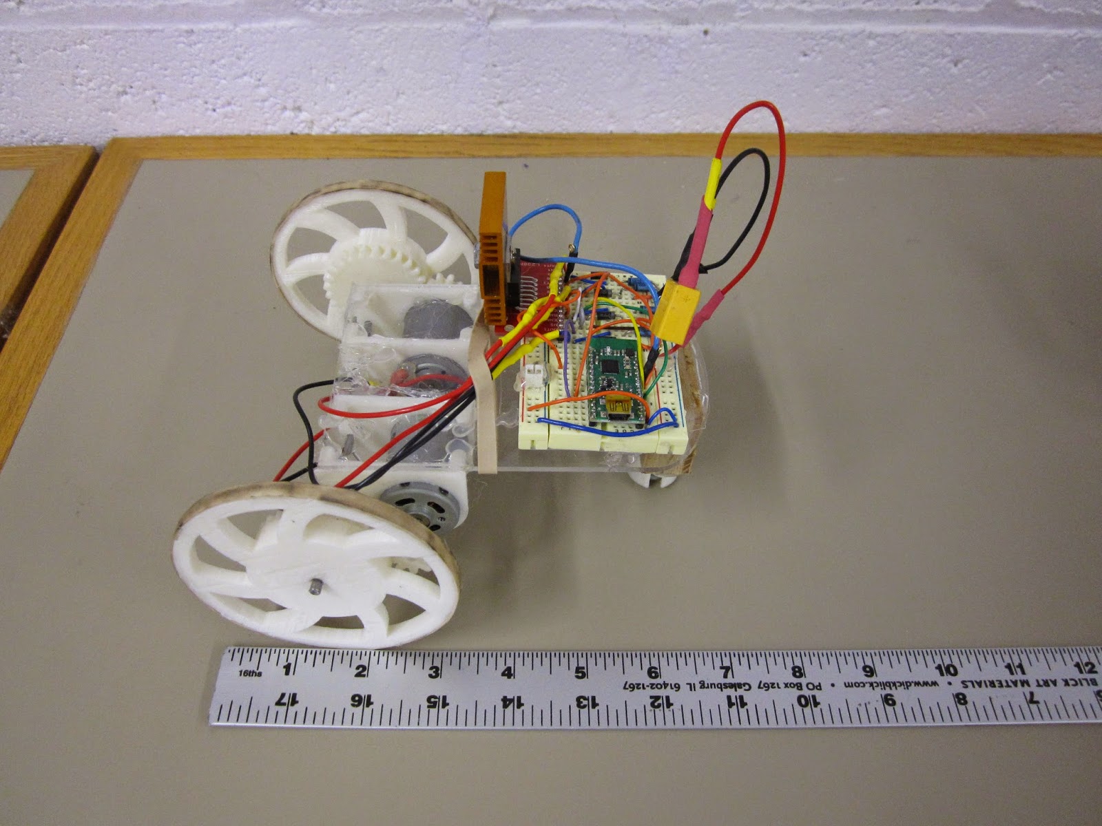
"Independent Study Cart"
This is the cart I just finished for an independent study I'm leading at the university. The key point of this design is to use the small, cheap, and ubiquitous "130" sized motors, like this one, though you can get them cheaper on eBay if you buy in bulk from China. Knowing that these motors would be a lot less powerful than the previous ones I had used, I needed to stick as many teeth as possible on the wheel. To do that without pushing my luck on 3D printer resolution and gear alignment issues, I made the gear ring as large as possible, so now the spokes are actually on the inside of the gear. The results are good, in terms of having big safety margins on gear alignment and robot pushing force. I put a very heavy 2,200 mAh battery pack on it and it moved quite well. I will probably source significantly lighter batteries for next week's order of remaining parts.
Now I just have to source the parts for 9 more, and work out nicer battery compartments, wiring harnesses, and ID tag standoffs for this bot. Then there is also some code I need to clean up and finish up. I'm pretty excited to see this project move to the next step finally! Though I will be playing around with new omniwheel and belt-driven robots eventually, for the next window of time my focus will be entirely on the robot brains (code and algorithms) side of things.


