Showing posts with label 3d printing. Show all posts

Wednesday, April 8, 2020

The Polyhedra Project (video summary)

I finally got some time to edit old footage...and build a garden...and breathe, think, reflect.

Here is a video summarizing my parametric 3d printed magnetic polyhedral assembly tiles. 

About 8 hours in Adobe Premiere to do the bulk of the work, then a few hours to make final edits and export it.


Tuesday, January 22, 2019

Rhombic Enneacontahedron Post #2

Alright, here's the code. It is a total mess, but I knew I just wasn't going to get around to even starting to clean it up, so I just committed it before I forget about it (and likely struggle to locate it in the future).

https://github.com/eshira/polyhedra/tree/master/Rhombic-Enneacontahedron

I figured out the degree of freedom I forgot about. When you truncate, you can move new vertices in along old edges some amount, which you can choose. I split edges in three, moving each new vertex in by a third (see the diagram from wikipedia that I included in the previous post). Splitting in three makes sure you create regular hexagons for the soccer ball step (the truncated icosahedron). You don't have to create regular hexagons, and by modifying this you can make slim and broad rhombi, as shown in the images below.

This explains why I didn't match the values for the angles that I found on Wikipedia for the rhombic enneacontahedron. I suspect that most of these rhombic enneacontahedrons people make come from just a few instructional guides or paper folding guides online, which often refer to slim and broad rhombi, so probably they aren't making regular hexagons in the truncation step, which seems to yield very similar rhombi so that you can't easily call them broad or slim.

Extreme cases caused by changing parameter of truncation step seem to be less 'round'


Here's the final 3D printed assembly, after gluing in the magnets. The edge length on the edges the white and red tiles share are 2cm long, for reference


It would be fun to print the exaggerated versions with very broad and very slim rhombi at some point in the future.

Want to make your own? The code isn't super clean, so the steps at a high level:

  • If you want to modify the truncation, you'll need to locate that section of the code, modify the appropriate line, and then get the code to spit out all the info you need on the angles and side lengths that are needed by the OpenSCAD script. There are a bunch of poorly commented areas where you can follow my pattern--I was working quickly and I just didn't make it easy to use yet. Sorry!
  • If you keep the angles as in the OpenSCAD script, you'll make a shape like the one I made. You need to make sure the user controlled side length is the same for the tiles of type A and B. You also need to make sure you match the magnet info between those two types of tile.
  • You can do this with just one magnet per edge if you want to save on magnets, though it won't be as strong and the tiles can pivot until locked into place by neighbors. You will need to go through my code because I didn't make it parametric either
Easiest way to do it? Keep everything exactly the same as my OpenSCAD code, render the STL and slice it for your 3D printer. Get at least 90*4 magnets, 3mm diameter by 2mm height, axially aligned. The magnet diameter and depth values in the script might still need to be adjusted to get a nice fit, depending on your 3D printer.

Wednesday, January 9, 2019

Rhombic Enneacontahedron

Over a year ago I decided the next 3d printed magnetic tile based polyhedron I would create would be the rhombic enneacontahedron.

In the past I created shapes mostly by looking up the dihedral and face vertex angles from the internet. Only for the most recent one, the parametric pyritohedra/dodecahedron script, I generated the points of the whole polyhedron and manipulated them, before creating the individual faces as tiles. For the trapezohedra, some of the ones I attempted to create had the wrong angles, and it wasn't clear to me if the issue was in the angles I had gotten from the internet or if my OpenSCAD script contained some errors. I decided though that the right way forward would be to build the tiles as I did in the pyritohedra script, by creating the full polyhedron and then computing the angles for the tiles myself.

I had just learned about Conway polyhedron notation and considered that the right way to build this would be to use that concept. But I didn't end up getting a library for Conway polyhedron notation, or creating a library for these operators. Instead I did everything a bit less abstractly and elegantly than I'd have liked, but I think that's normal to expect for a first draft.

I switched from OpenSCAD to python at this point, because I find it impossible to do anything with for loops in OpenSCAD (highly inefficient and slow). For creating polygons in 3D space I used pyny3d, which is already integrated with matplotlib for drawing. And I use numpy for math stuff. I finally switched to python 3 for this and wrote every print statement incorrectly the first time...

We begin with the icosahedron:


For the icosahedron I started with a list of 12 vertices as listed on various places online.
Each of the below descriptions of vertices in format (x, y, z) expands into four vertices given there are ± options in two of the dimensions for each one.
(0, ±1, ± φ)
(±1, ± φ, 0) 
(± φ, 0, ±1)
Where φ (phi) is the golden ratio, 0.5*(1+sqrt(5))


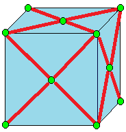
The first goal is to truncate the icosahedron. I came up with my implementation of truncation by interpreting the picture and one line description from Wikipedia, which I'll include below, and is drawn on an example cube:


Truncate cuts off the polyhedron at its vertices but leaves a portion of the original edges.[10]

I describe truncation like this:
For each vertex, find every edge is is a part of, and create a vertex one-third of the way inward on that edge. The new shape's vertices are the newly created vertices.
The new shapes faces I separate into two categories.
The first category are created by drawing edges between all the new vertices spawned off a single old vertex. In our case, the icosahedron has vertices at 5-edge intersections, so these are five sided shapes (pentagons).
The second category are the truncated versions of the original faces. For each original face, consider each original vertex. That original vertex spawned some new vertices, but only two lie on this original face that we are currently evaluating. The new face that will replace the old face is defined by all of these new vertices corresponding with the old face, that still lie on this face.
We had triangular faces with the icosahedron, so with two vertices per original vertex multiplied by three original vertices, we have created six vertex faces (hexagons).


The truncated icosahedron is a soccer ball, shown above in red pentagons and blue hexagons.

Now we must run a join operation on the truncated icosahedron. Again, expanding from only the short wikipedia entry:

Join creates quadrilateral faces. 

That's not a lot to go on... To better understand it I considered a similar operation, kis:


Kis raises a pyramid on each face

Okay, so join is like kis without the original edges. The old vertices can stay put, but the new vertices, created in the middle of each face, need to be lifted. But by how much to lift them? And where to put them to center them on the face?

I had gone over the math for finding the vertex on the face, when I went over the math to define the dual operator. Luckily for me the pentagons and hexagons are regular, so I could just take the mean of the points in this case.

The insight for how to lift the vertices came from the symmetry. Some of the newly created quadrilaterals will go from one hexagon center point to another hexagon center point. To preserve symmetries, I assumed that all hexagon center points will be lifted the same amount. I drew a quick diagram to figure out the computation for how far to raise them in order to make all four points coplanar (otherwise, we don't have a valid face. At time of writing, this site which I enjoyed using in the process of learning about Conway operators, seems to have some nonplanar 'faces', so it looks very strange).

New quadrilaterals connecting old hexagon centers to old pentagon centers must also be created, utilizing two old vertices that come from the edge shared between the adjacent hexagon and pentagon. Since we finalized the height of the point raised off the hexagon center, and we know the two points from the shared edge are the same as they were before, the only thing to do is compute how far to raise the pentagon center along the norm of the pentagon face until it lies on the plane defined by these other three points.

To draw the faces I needed to keep track of which faces were adjacent to which other faces, so I created some dictionaries and populated them with simple for loops because I'm not concerned about optimizing my code at all given what I'm using it for.


The next step was to compute and print out the angles I needed to create a tile. This was just a question of identifying the right vertices, edges, and vectors and computing various norms and cross products.

For the tiles I moved back to OpenSCAD. I reused my rhombic triacontahedron tile code for the parallelogram faces (red). For the kite faces (blue) I created some new, but very similar code.

Here's the info printed out, there's definitely going to be some rounding error but not significant to my purposes.

There are two dihedral angles:
Red to blue faces: 159.4455573432933 degrees
Blue to blue faces: 160.81186354627906 degrees

The red parallelogram faces have an acute interior angle: 56.67993474152847 degrees
And the complement (computed just to check if correct, but not needed as additional info): 123.32006525847153 degrees

The blue kites are more interesting. The skinniest angles are the tips of the five pointed stars they create.
56.67993474152846 degrees

The opposite angle, which lies in the middle of those stars where they meet in groups of five, is close but certainly not the same angle:
69.7316519531762 degrees

It is a kite, so symmetric in this remaining dimension, and both of these larger angles are the same:
116.7942066526476

This didn't seem to match the info on Wikipedia and I'm also not seeing such a clear distinction between 'slim' and 'broad' rhombi. I wonder if I did something wrong, though so far everything is internally consistent for my construction. I wonder if there's an assumption I made that got rid of one degree of freedom....

Finally I needed some info about the edges. The red edges are all the same length. And, they match the length of the slightly longer of the edges of the blue tiles. The other type of edge is the ones that the blue tiles share with each other. I call this a 'short edge.' 

I computed a long side: 0.4339800705873414
And a short side: 0.36037602329028573

And the ratio of short to long as their ratio:
0.36037602329028573/0.4339800705873414

I ordered a few kinds of magnets in sufficient quantity (I need 90 faces * 4 magnets a face, but I might also double up and do 2 magnets an edge or 8 magnets a face). While I wait, I am 3D printing some tiles just to tape together and see if the angles work. So far it is looking promising.

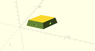
parallelogram faces model, shown with magnet holes


 kite faces model, shown without magnet holes


They look fairly similar to the untrained eye...

Taped together with masking tape as a test....red parallelograms and white kites. They were all printed in white, and then I used a sharpie to color the parallelograms in red.


A five pointed star of kites.


Since these come together nicely, I think I have all the vertex angles and the dihedral angles correct.

I've always used either masking tape (testing) and magnets (super-glued into the slots) to construct these, but somebody who printed one of my designs and tried gluing them together noticed that there appeared to be an accumulating offset problem that grew as the shape was constructed and made it so it wouldn't close. It seems that you need to leave some flexibility in order to distribute errors (that come from the manufacturing process or mis-alignment during assembly). Some ideas I haven't tried include: putty, velcro.

Once I've had a chance to build the whole thing, I'll follow up with another post, and clean up the code and commit it to GitHub as well.

Wednesday, June 7, 2017

Indoors Navigation Robot ("Driving Drawers") Post 1

[Foreword: you may notice the fonts are mismatched in this post. Or maybe you noticed that the images in all the posts in this blog, when viewed on a larger screen (as opposed to a small mobile device screen), are placed haphazardly within the body of the post. This is because Blogger leaves much to be desired when it comes to the WYSIWYG post editor. In part because WYS ("What you see") is not always WYG ("what you get") in the context of Blogger's post editor, but also because there are very limited options for aesthetic image layouts in the body of a post. I am planning a Jekyll based webpage for this blog in the general future that will fix these problems. Until then, this is a cheap and easy way to make sure I keep a blog at all.]


I had an idea for a chest of drawers that would drive to my location in a space (assumes no stairs).

Here's the first part of my progress on that project.

Physical Build

I started by dissecting my collection of Roombas and taking the wheels from two different models and hot gluing them, along with some support material, to the base of a plastic chest of drawers.


I purchased a Raspberry Pi 3 and a PiCam, and while I waited I put together a 3D pan-tilt design from Thingiverse. I'll provide a link (link to thing), but keep in mind I do not recommend this design. Unless your 3D printer is very precise, you'll have to do quite a bit of filing and sanding to get it to go together. The pan servo will absorb all the impact whenever it hits something, and will fail (mine did). If you can find a ring of the right thickness and diameter to stick in between the orange disc and blue plate in the photo, the problem is mitigated (I used a bearing I found in a bin--way overkill as it isn't even acting as a bearing--but a quicker solution than cutting my own ring on the lathe).


Not entirely certain of the layout I wanted, I just taped everything in place with masking tape. The battery is stored underneath, in the topmost drawer of the robot. It's a 30,000 mAh battery I bought for use with my smart phone. It has a port that will source 2.5A, which is needed by the Raspberry Pi. I paid about $75 for this model; you should be able to find comparable batteries by other brands if that one is not available (sometimes, when an item is out of stock, a few vendors will offer it for an inflated price, so beware. The price on Amazon for this model was briefly $399 before dropping to $69.99 again). 
I pulled the Arduino Mega out of a project I'm not working on at the moment, though it is of course overkill for this application. I wasn't sure how many sensors and actuators I wanted on board, so this 54 I/O pin Arduino allows for quite a bit of room to grow the project. The Raspberry Pi 3 itself only has one PWM enabled pin available to me, so the Arduino is convenient for handling all the low level stuff. It talks to the Raspberry Pi over the USB. The micro servos are powered from the Arduino Mega which are in turned powered off the Raspberry Pi. The micro servos stall current is low enough for this to be possible with the Arduino Mega.


 The Roomba wheel motors are safe at 12 volts (the Roomba battery voltage), so I put another battery in the system just for them. The battery is a 3 cell Lithium Polymer battery, which measures in at roughly 11.1 volts when the battery needs to be recharged and 12.6V when the battery is fully charged. The motor drivers are L298 chips on those red-colored Sparkfun breakout boards, with the heatsinks mounted to them.


So at this point the robot was driving, but only in a straight line. Turns would drag at least one wheel and make a terrible noise. Only very slight turns worked. This was fairly predictable, but trying to make it work anyway was very much in keeping with my glue-and-tape, then iterate style of prototyping. Jesse helped me put together a steering mechanism in a very short amount of time. It worked, so that evening I took the robot out for an inaugural journey around Sector67, using it as a sort of telepresence robot as I controlled it from my desk.


Then I broke the steering mechanism gearmotor by switching it back and forth too fast when I got stuck in a corner. The gear before the final output shaft broke into a bunch of tiny pieces.


I replaced it with the gearmotor in the image above on the right that has the partly blue casing. Now that I had a working robot again, it was time to work on the high level path planning and code. I'll put that in the next post.


Friday, March 10, 2017

Trapezohedra

Another set of magnetic tile polyhedra. This time, three different trapezohedra.

https://en.wikipedia.org/wiki/Trapezohedron

http://www.thingiverse.com/thing:2168615


https://github.com/eshira/polyhedra

I used this resource to define the kite and dihedral angles, but the hexagonal and heptagonal did not work out (and I believe the octagonal also has issues). Fixing them is on my to do list. I plan to write a script that actually generates them from the antriprisms.


Monday, October 17, 2016

Nefertiti 3D printed

The Nefertiti Hack refers to the release of a high quality 3d scan of the bust of Nefertiti without permission of the Neues Museum who held the piece. Read more here. I believe that we as a society should feel obligated to digitize, catalog, and make it easy for the public to access art. I'm a big fan of the work done by Cosmo Wenman and his commentaries on these topics.

Anyway, once it was released I printed the Nefertiti head in 80% scale. I split it up into 8 pieces (using the Boolean object modifiers in Blender and a large cube object) that would be manageable for our army of Flashforge Creators here at Sector67. The pieces were the neck, face, left and right head sections with ears, middle left and right hat sections, and top left and right hat sections.

They were printed in ABS black plastic and glued together with acetone. The hat pieces warped a lot and the surfaces were not flat enough, so those were glued together with dowel rod pins and hot glue. I used Tamiya putty to fill in cracks and then did a lot of hand wet sanding to get the creases less noticeable.


Putting Tamiya putty on the surfaces to fill out striations and then sanding worked fairly well. At this scale, filament lines aren't that obvious anyway. It felt like I was rubbing lotion onto her skin. Only it was nasty toxic smelly lotion with fumes that cause some neurological damage. I did most of this outside but it isn't really worse than the other poisons I use like spray paint or wood stain or whatnot.


I don't have more photos but I basically left it at a very gold color (after a few more coats of the paint above, which is a brass containing paint). I was going to patina it but it is making rounds at various makerfaires and other events and chips caused by falling are easy to repair when the color is a flat brass, but would not be easy to fix if I had to also redo the patina.


Tuesday, April 19, 2016

"Pip Girl" (3d printed Fallout 4 Pipboy)

This 3d printed Pip Boy (or Pip Girl) was made for my sister. Her birthday was about half a year ago, and I started this several weeks prior to that event, so this project actually went fairly quickly compared to some other projects on this blog...

The files are from http://ytec3d.com/pip-boy-3000-mark-iv-assembly/


Gluing: superglue, acetone, and hot glue.
Paint: spray paint, clear matte coat, and some touch up with acrylic paints
Modifications from original:
  • Velcro latch (3d printed latch deemed too weak--wouldn't want it to break and fall with a smartphone inside)
  • Did not print transparent PLA light covers (hot glued orange LEDs with orange plastic diffuser in directly instead)
  • White vinyl fake leather cuff with foam padding -- makes it much more comfortable and a much better fit.

Wednesday, March 30, 2016

Patinas and metallic paints

I've been experimenting with metallic paints on 3d printed objects and spray on patinas. Photos and then a description of technique and products below.


My friend purchased some Sculpt Nouveau Metal Coating (Brass, B) that she didn't need, and I applied it to all the pieces above. Tips for using that paint:

  • Sand surfaces with 220 grit if smooth. Surface that are too smooth will be hard, though not impossible, to paint thinly.
  • Brush a layer on as thinly as possibly. The print surface will show through. It will dry fairly quickly. If you can see brush strokes while the paint is wet, that is too thick (unless you like that look). Once dry, if you want to get rid of a brush stroke or drip you'll have to sand it down.
  • Once dry, apply another layer. The deposited metal particles will roughen the surface so that subsequent layers of paint adhere better and get more coverage.
  • The brass paint got brighter as it dried. It sometimes had a dull look when wet but that goes away.
  • The patinas must be applied when the paint is wet to stand a chance of interacting with the metal particles, so apply a final thin wet coat and patina immediately. If too thick, the paint has a tendency to crumble up (cottage cheese is another description I've heard). Some patinas will also just deposit some color on the surface and so would be at least partially effective even on a dry coat of paint.
The patinas I used were the following products from Sculpt Nouveau:
  • Tiffany Green
  • Jade Green
  • Deep Brown
  • Mahogany
  • Vista Rust (Bender head only)
I mixed and matched the for different effects on the different objects above. The Jade Green leaves obvious green deposits immediately on the surface.

Thursday, January 15, 2015

More MOARbots


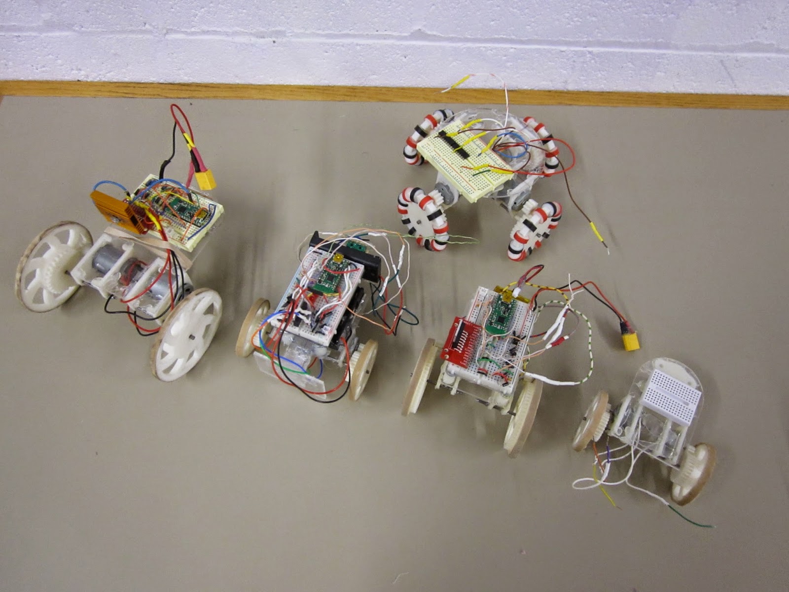
The 5 'models' of MOARbot that I've made so far. MOARbots doesn't really come in 'models' so I put that word in quotes. Overall the above robots represent my exploration of a bunch of different design elements. MOARbots as a project is just the framework/resources/suggestions one might need to pick and choose their own elements and make their own set.

When I have a need to create a set of robots though (for AI control, remote control games, whatever else), I do tend to want them to all be identical. So then I'll refine one design, and print out n  many more. In that sense it has become convenient to refer to the designs as 'models.'


"Big Cart"
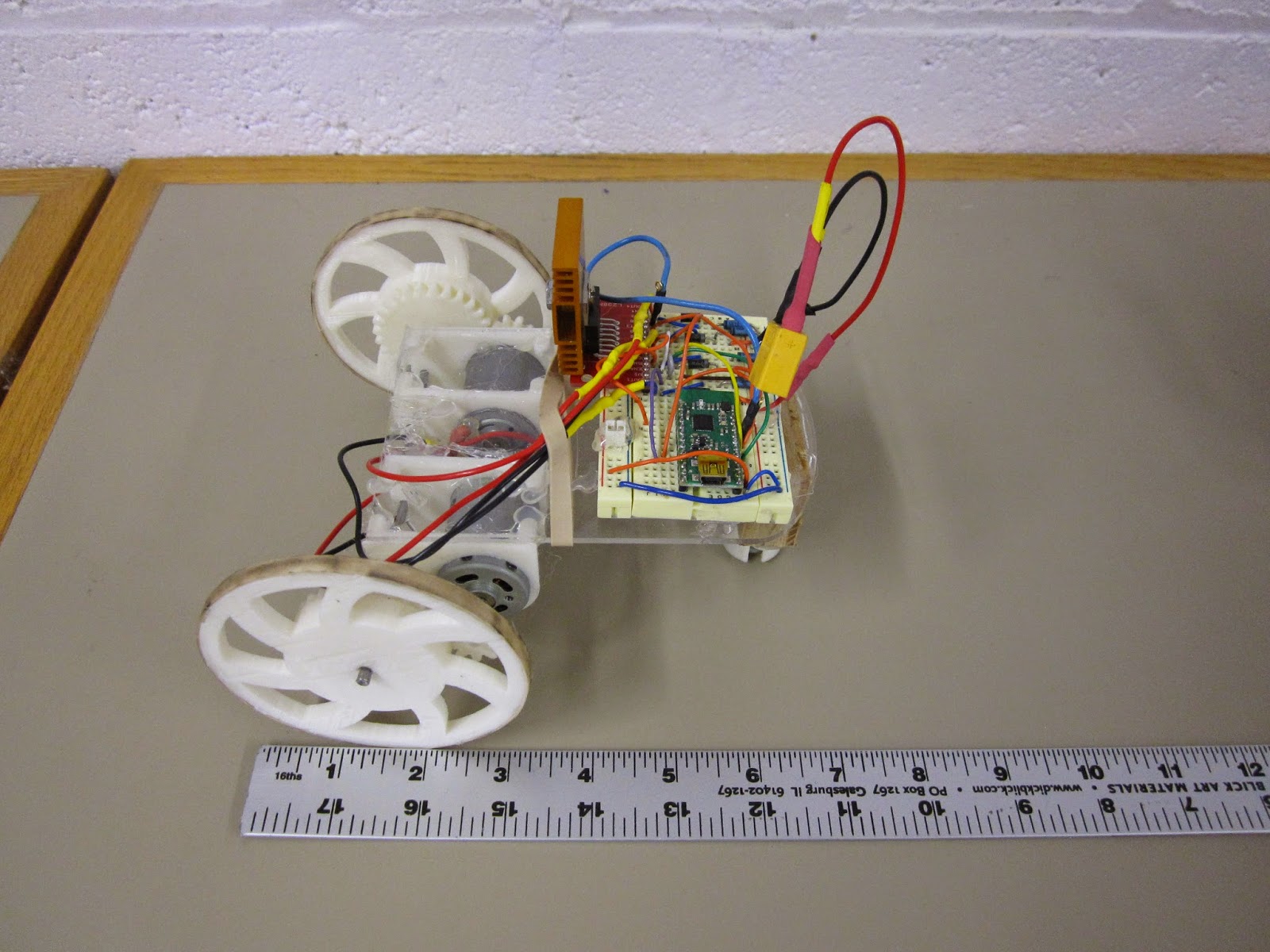
Above is the very first MOARbot. I sourced parts to make a full set of seven identical robots like this one. The motors are the very beefy RS-385SH by Mabuchi. These are geared with just a 3:1 ratio (I tried a 2:1 but with the battery weight, the thing stalled too easily). As a result it is very zippy. Notice the black marks on the rubber band tire--some Sector 67 members had fun driving this thing around quite a bit. Heat sink is definitely necessary. The stall current of each motor is 4 amps, which means that at full stall they will burn out the motor driver, which is spec'd at 4 amps total for both motor channels. The proper solution would be to use the current sensing pins to stop the motors when they draw too much current. The quick-fix solution I implemented at the time was to remind all the drivers that they should hit the brake key every time the robot ran into something.


"Omni Prototype 1"
This is the first omniwheel MOARbot prototype. It used 4 unknown motors pulled out of a bin. The omniwheel black and red 'beads' were spray coated with some products to make them more tacky, but that ultimately did not provide enough traction. A quick test showed moving a pair of motors took about 4 amps continuous current draw. The wheels slipped a lot on most surfaces as well. I came up with a much better design right after, but haven't yet finished work on that project (very very close though).


"Small Cart"
This is the smallest design so far. The motors were pulled from a bin, and only one worked. The robot was successfully able to drive in circles with 2 AA batteries (alkaline). This convinced me to try some smaller motors for similarly sized robots. If I were to go smaller than this, I'd switch away from 3D printed gears altogether and use rubber belts (like this robot that uses them with little CD drive motors). A robot like that could be built without any 3d printed parts, which would be appealing those who don't have access to 3d printing. A MOARbots project to source the parts for and build a set of those will happen most likely this year.


"Bumper Cart"
This is part of a set of 4 robots built around the FK-180SH. They are meant for playing remote controlled bumper cars, MarioKart style. The green pair of switches on the left are the target, and the acrylic panel on the left is the front of the robot. Robots race around the arena trying to hit the other robots' targets. After n hits to your target, your robot is out of the game (stops in its tracks) until the game is over and the players all agree to hit the reset button on their controllers. A pair of LEDs can be used to indicate robot 'health.' Why only 2? There are only 2 'high current' (20mA) output pins on the Wixel, and that breadboard was getting too crowded for me to start adding in some transistors.
Unfortunately the bumper carts did have one minor issue--for reasons not yet determined, the cart couldn't actually move under its own weight with the full circuit hooked up, but could move when the batteries were connected directly to the motor terminals instead. I will have to do some science to it, but I bet putting a nicer battery (2 or 3 cell lithium polymers) will fix the problem.

One cool but not completely necessary feature of the bot above and the bot below is a disconnect-able breadboard. The breadboard sits on top of three standoffs, and is held in place by magnets. The motor and battery leads are long enough to allow the breadboard to be moved around. I like this system because it means I can work on the circuit without risking pushing down too hard on the robot frame (this is mostly a fear because the diodes I bought have very thick leads and the required force to insert them into the breadboard is high).


"Independent Study Cart"
This is the cart I just finished for an independent study I'm leading at the university. The key point of this design is to use the small, cheap, and ubiquitous "130" sized motors, like this one, though you can get them cheaper on eBay if you buy in bulk from China. Knowing that these motors would be a lot less powerful than the previous ones I had used, I needed to stick as many teeth as possible on the wheel. To do that without pushing my luck on 3D printer resolution and gear alignment issues, I made the gear ring as large as possible, so now the spokes are actually on the inside of the gear. The results are good, in terms of having big safety margins on gear alignment and robot pushing force. I put a very heavy 2,200 mAh  battery pack on it and it moved quite well. I will probably source significantly lighter batteries for next week's order of remaining parts.

Now I just have to source the parts for 9 more, and work out nicer battery compartments, wiring harnesses, and ID tag standoffs for this bot. Then there is also some code I need to clean up and finish up. I'm pretty excited to see this project move to the next step finally! Though I will be playing around with new omniwheel and belt-driven robots eventually, for the next window of time my focus will be entirely on the robot brains (code and algorithms) side of things.